I would like to have one of these checking the hourly pricing API https://hourlypricing.comed.com/hp-api/ every 5 minutes and then adjust temperature based on a running average of the current hour rates. There are times it unexpectedly spikes up, and times it goes negative. I would like to consume more power when the cost is negative, (precoolling) and less power when it spikes up by letting the temp drift up. Spikes are random and only last one hour, so I am paying a premium to cool my house at 9 in the morning sometimes, and that just doesn’t make sense, the AC can easily lower the temp back down especially early in the morning.
The rate I am charged is the hourly average of prices displayed every five minutes. For the first couple of five minute increments in an hour, we could look at previous hour average to keep ourselves from wandering to far out, but after that just work to current hour average. It could be more complicated, but this would give us 80% of the benefits with only a smaller percentage of the work.
If we wanted to get slightly more fancy we could look at time of day, and decide if we want to ignore the rate to some small degree, as it is likely to climb even higher later on. There are plenty more tweaks that go beyond that, like weather forecasts, but that gets more difficult.
I am happy to contribute code to make this happen.
OK, a first approach is very easy.
First thing you need to do is write a script that gets the value from the API link you sent me.
Then, add this script as a “thing” in your OH2 and store its value (you may need to create an “item” too to store it into). Add a 5 minute period there too.
Lastly edit the [OH2_dir]/rules/default.rules and add a check for its value everytime it changes value and if it translates to cheap pricing, adjust the setpoint to either a low value (65F) or a relatively lower value like -5. I would advise to store previous setpoint in a variable in order to go back to it when the pricing goes back to standard values.
One last thing I need to draw your attention. The HestiaPi Touch does not support yet both heating and cooling. The rules you see there are for heating so change the greater than (>) to less than (<) and vice versa to make it for cooling.
I would appreciate your feedback and/or questions to make this work.
Sounds cool, can I buy a US thermostat so I can do this?
I am fine using it without a case if that is required, my kids are big enough to know not to try to eat it off the wall or anything.
The case is one thing. It is indeed not ready yet.
It does support 4 separate contacts (Green, White, Yellow, Red) @ 24V AC with 3 relays but it also requires mains supply too (100-240V AC)
Another thing is that the LCD does not allow to turn the fan and/or heating/AC separately so you will need to customise it the way you want it yourself (with any help from me in terms of questions).
if you are happy with that read the full page of the non-US model in the shop to inform yourself on the features and bugs.
I just want you to be sure you know what to expect from what you are buying.
I haven’t used my furnace in fan only mode in this house, so that isn’t concerning to me right now. I have an outlet directly below the thermostat so it is easy enough to plug it in. It also sits on a fairly open throughway to the upstairs so I can run anything I want to it directly. One of my wifi access points is cabled through the same cavity, and I left a rope (paracord) hanging so it is really easy to pull things up from the basement. (the AP covers the hole when mounted on it’s plate, just don’t tell my wife)
Nothing else on the UK product page worries me. Its a development project, but it has a web and mobile interface, so I doubt we will ever touch the screen.
Wise on-hold cabling design Very future-proof.
As long as it looks pretty wives don’t really care
About the fan… how does it work exactly in standard homes in both heating and cooling mode?
I will post here some pictures of the US model within the weekend so that you know more details.
Lastly, there an issue with the responsiveness of the commands if they are initiated from the LCD. It may take up to 2 seconds for your touch to register. Of course all other commands from the smartphone or your laptop/browser is instant. It is an issue with Chromium as this is the application that loads and handles the touch UI.
Once you are happy please purchase the UK model adding a note asking the US model and I will swap them for you and confirm. Thank you for your trust.
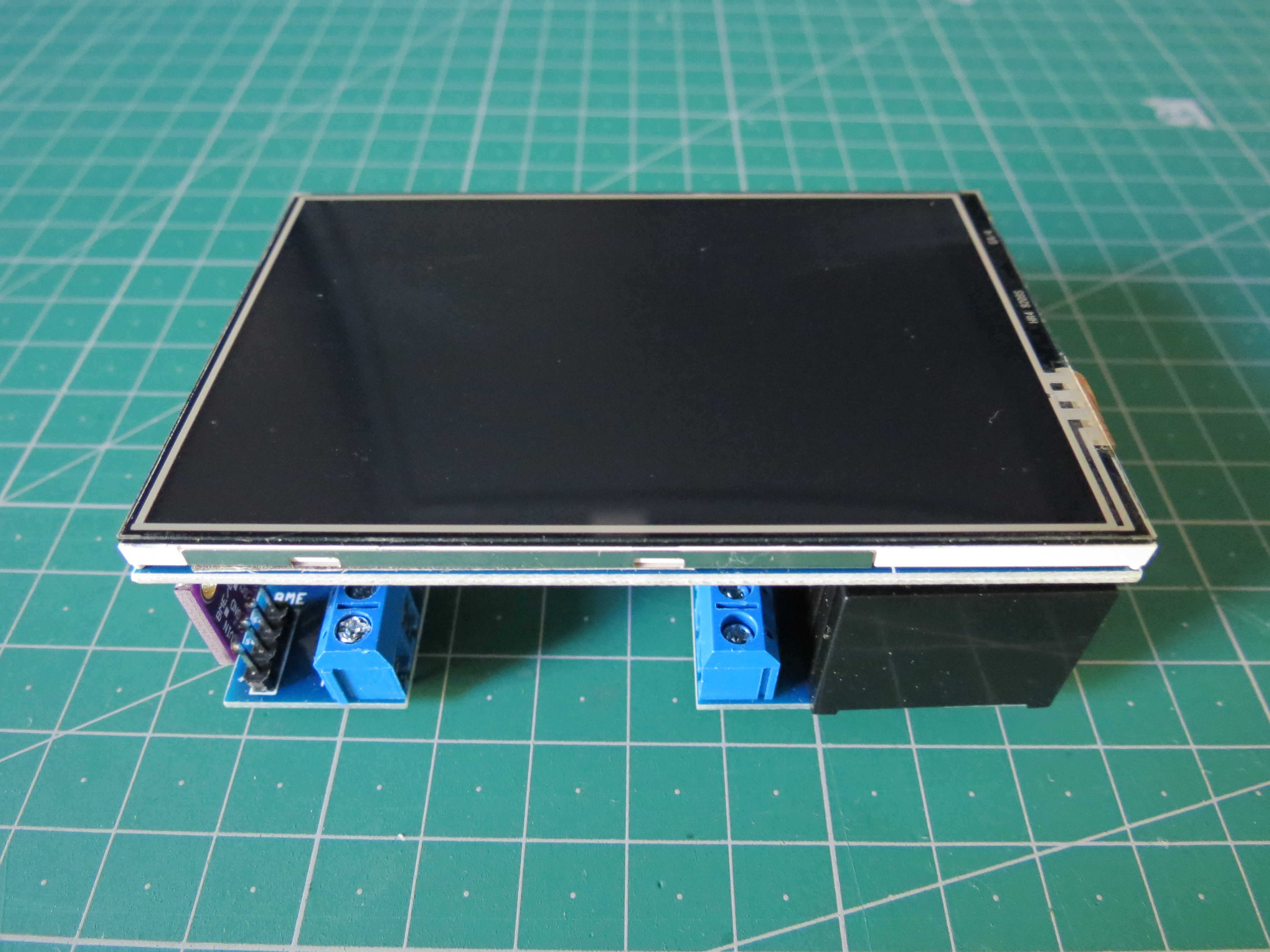
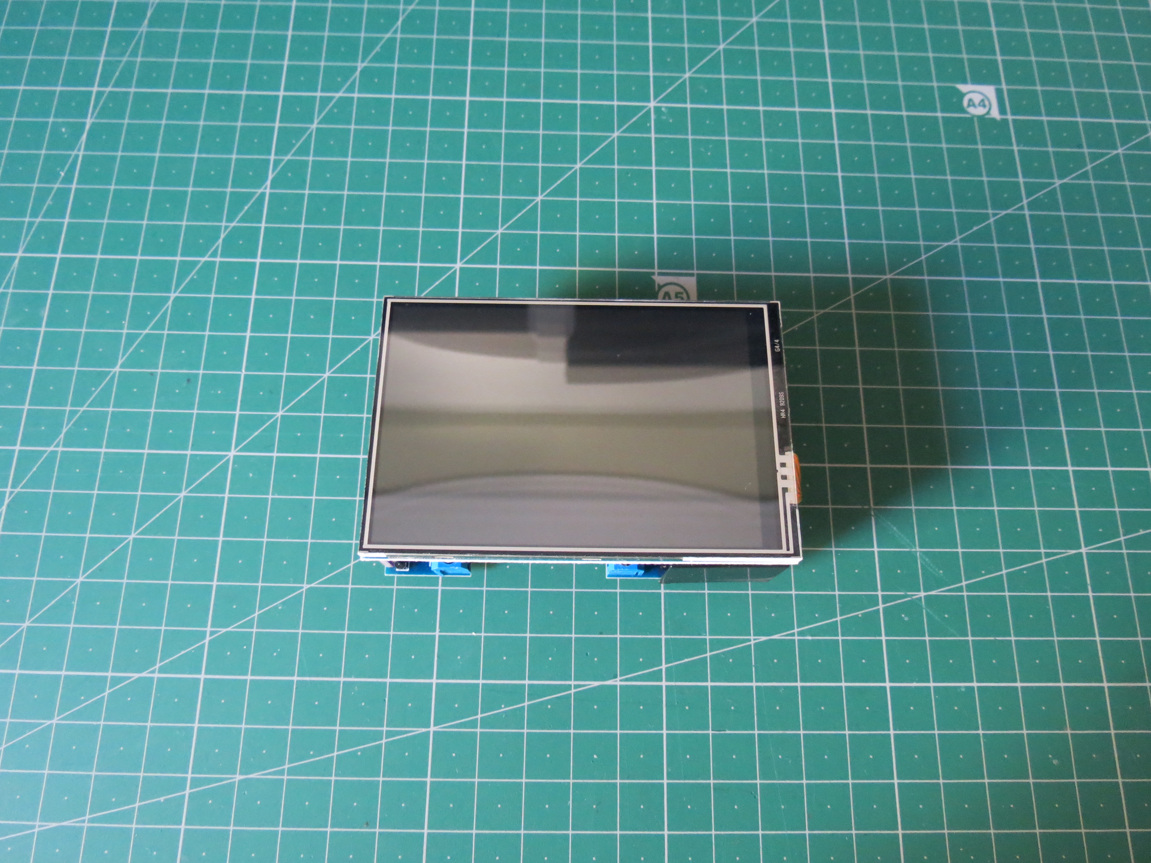
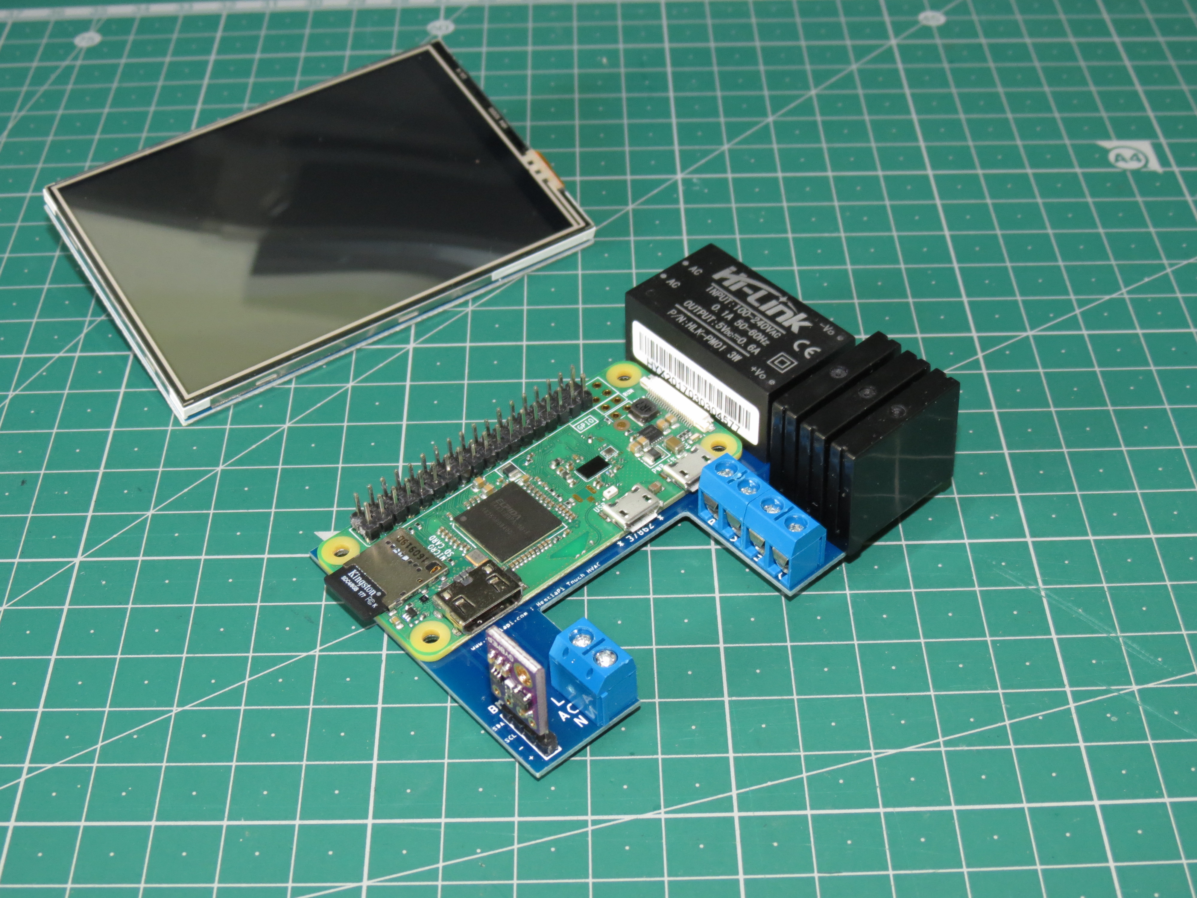
Here are a few quick photos.
Please note that the relays are now solid state (SSR made by OMRON - G3MB-202P) which means two important parameters:
They only control AC (not DC) currents up to 2A. I have never seen DC used for signaling in HVAC systems so this shouldn’t be an issue.
The relays provide only 2 normally open (NO) contacts. When triggered they close the circuit.
Both above features are standard in all HVAC systems so I made the assumption to force them, but as HestiaPi in intended for hackers and hackers may want crazy (but uniquely useful) things, I want to explain what to expect.
A few more comments:
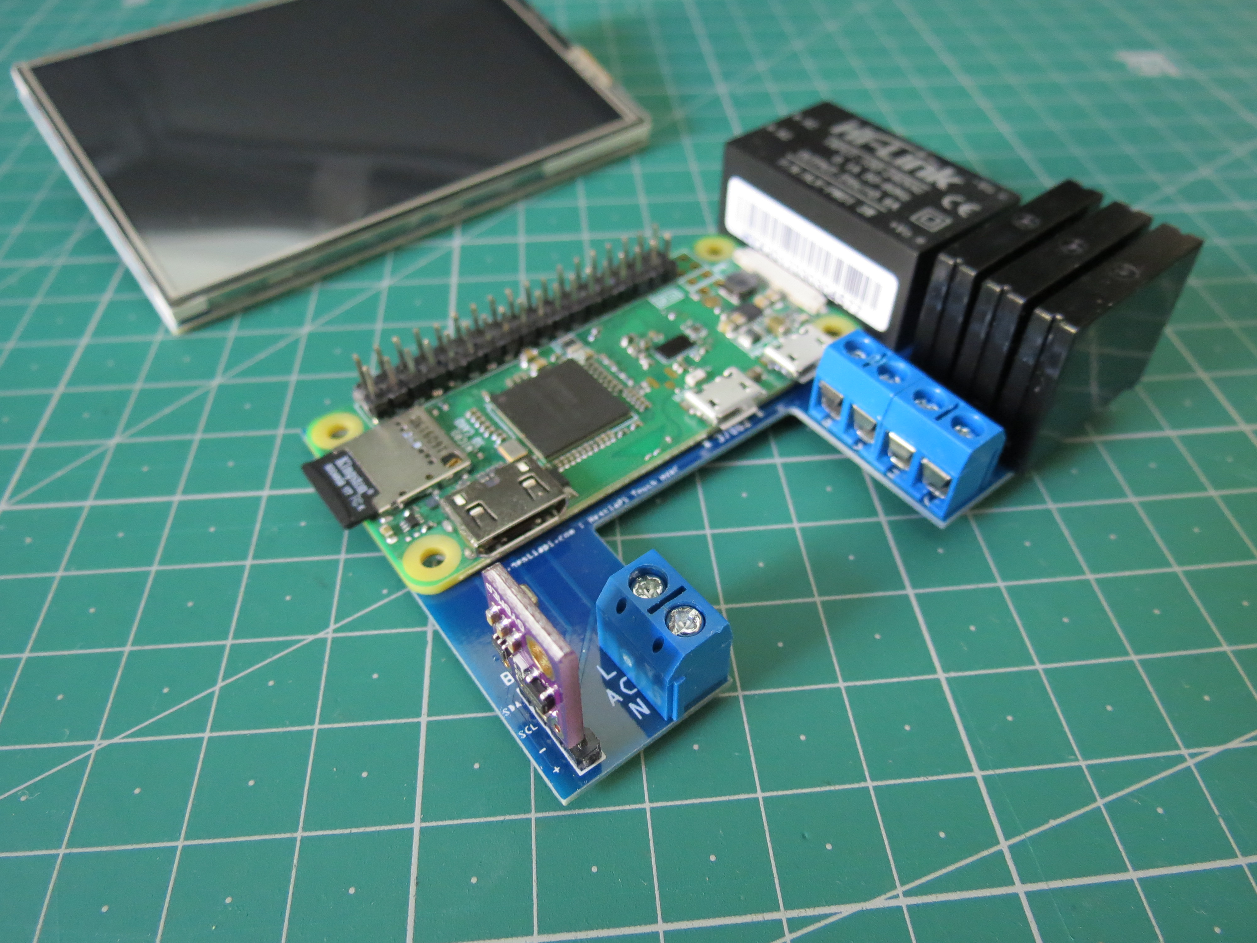
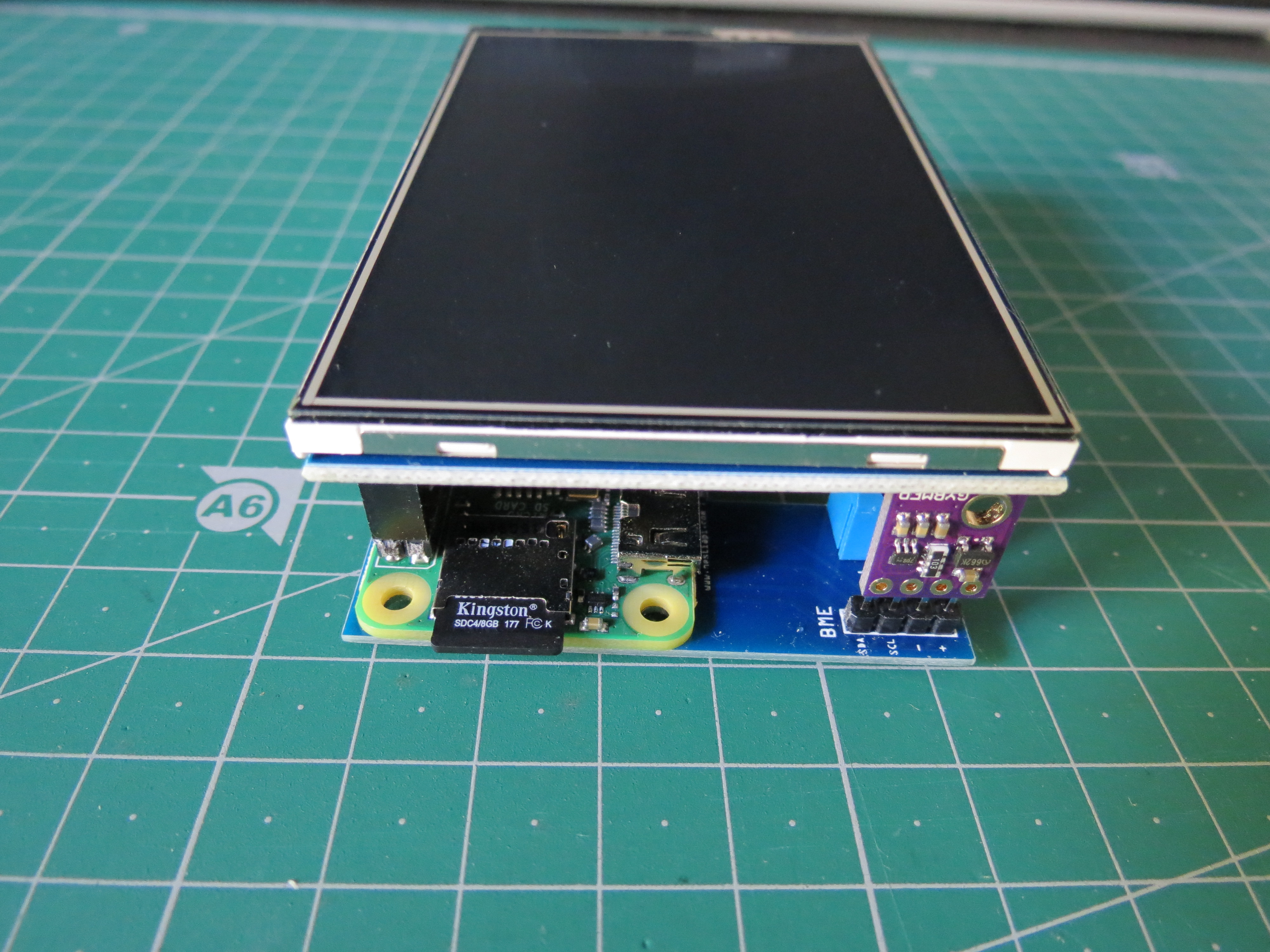
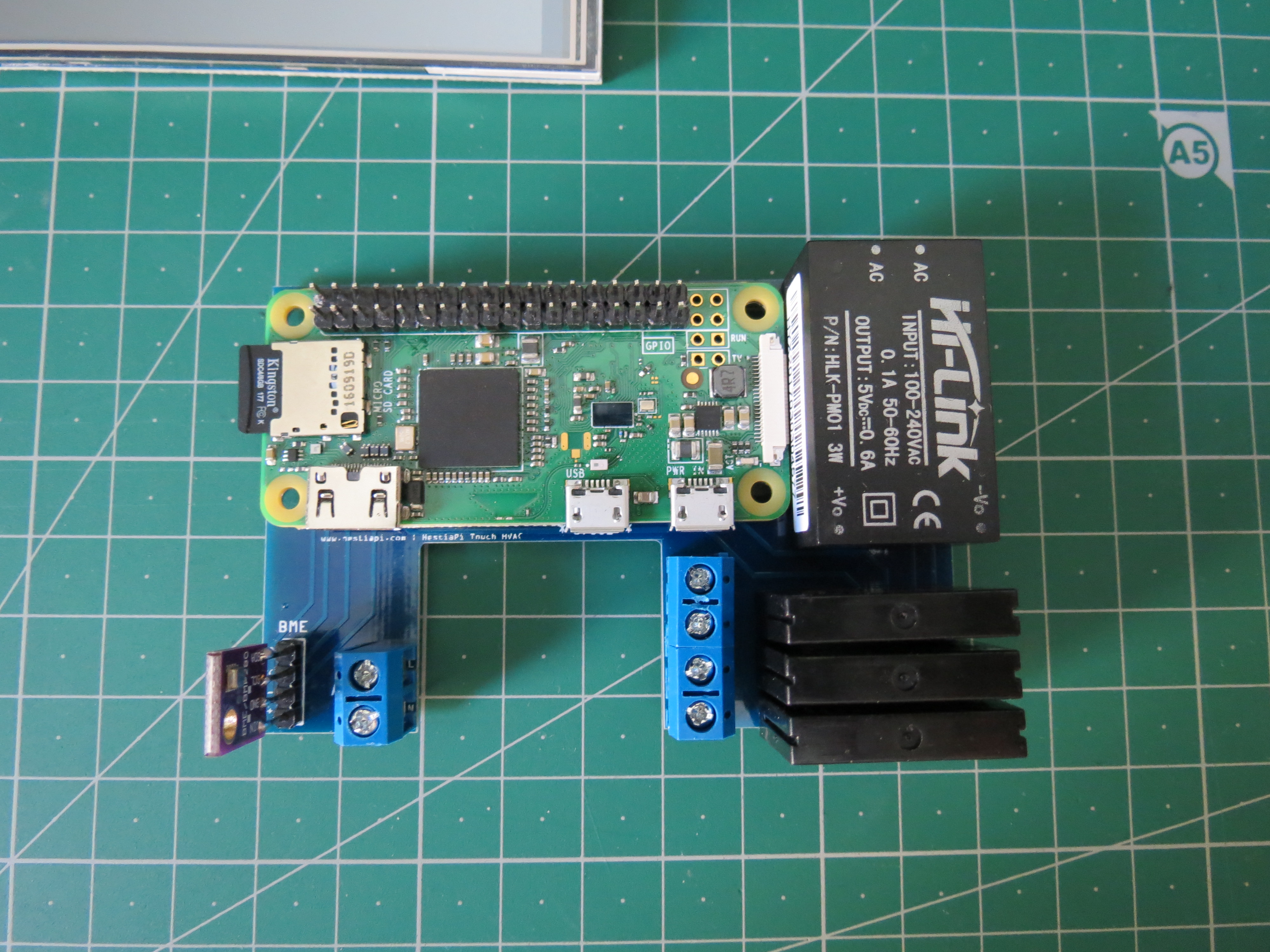
On the last photo, the 2 terminal blocks on the left is for AC (100-240V AC) and the 4 terminal blocks on the right is for R (red), Y (yellow), W (white) and G (green) from top to bottom. The writing in unfortunately printed underneath them, sorry.
The sensor (BME280) will not be soldered directly as in the photo but with pin headers and short extension wires (dupont)
The Raspberry Pi Zero used is the W version which include WiFi and Bluetooth on board. Yoohoo!
The screw terminal on the strip of four closest to the Pi itself is the Red?
This unit is designed to snap into whatever holder I construct for it? I don’t think I see any screw holes that go through.
Ironically I have an Omron G3NE-220T-US on my desk. It is on my desk because it was a bit to good at it’s job. I had wired it up to my low voltage wiring circuit as the trigger (through an AC to DC converter) and connected the load to the outside lights on my house. The problem was that even with the Low voltage lighting off, it was picking up enough noise to intermittently trigger the lights and make my house look like it was ready for Halloween. (the exterior bulbs are all LED) I swapped it out for an actual relay that triggered on 12VAC and since it requires actual current to trigger, it acts as expected. I am guessing you aren’t having issues like that, but something to keep an eye on if the trigger lines are getting any voltage induced into them.
The 4 x 2.5mm holes of the Pi are going through the PCB too. You can barely see it in the last photo. It is too dark indeed. You can reuse the Base 3D printable file from the first version but only 2 holes are available. Simply drill the plastic for the other two if you want all 4 points. There are also 6 holes for fixing it on the wall. I assume only 2 should be enough, but I provide various locations in case you can reuse existing holes on the wall from previous thermostat. https://hestiapi.com/3d-12032017-hestiapi-touch-base-stl/
The triggering signal comes from the RasPi itself and any external current is isolated from it. I haven’t got any complains yet or any comments on the forum. Still an experimental model and full refund will be offered if problems found. Nothing serious has come up yet.
I had the SSR shoved in to a wall switch box with three switches, and a whole bunch of wire, so it is certainly a high noise environment. I got it to “work” by pulling everything out of the box and getting some separation between the LV and mains wires. Since that isn’t a practical implementation, I located an appropriate and compact relay, which has been switching my exterior lights ever since. I wired the relay in front of the outdoor lighting switches so I can still opt to turn off the outdoor lights, but they are always off when the LV lights are off.
So long as you didn’t route the switching signals parallel and in close proximity to the mains current I wouldn’t be worried about it. Just my experience with strange stuff and SSRs.
Good news on the screws, much easier to deal with that way when building stuff. It is just drywall so not a big deal to patch and move holes around. Look forward to setting this up.
 Very future-proof.