Hi Everyone, I am looking to purchasing all the parts for the HestiaPi myself as I want the experience putting it together instead of buying the kit.
I have 3 questions:
-
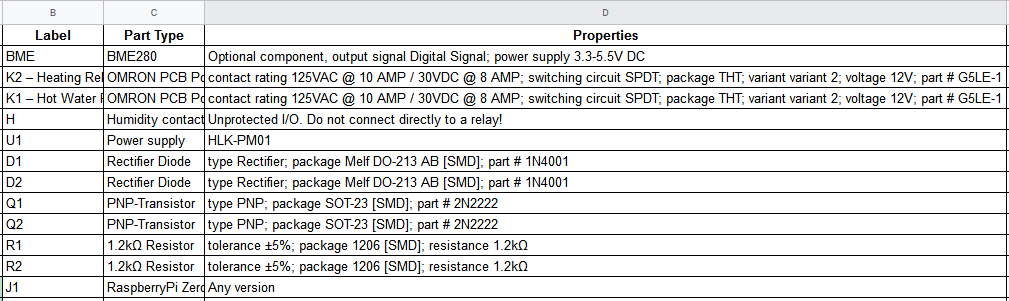
In the DOM, the BME280 is stated to be an “Optional component”. Why is this considered optional as you would need it to grab the temperature?
-
In the DOM, the Label H says to be a Humidity Contact and is shown in v6.0 – PCB-20180714 on the main site PCB image. What is this for? I see it links to pin 12 on the raspberry pi zero through the PCB tracing but as for components/wires that go to that hole, I don’t see anything for it. I put a picture of the list below.
-
Where would some of you guys suggest purchasing the following parts as I am looking around, but just want to ensure that I purchase the correct part:
- Rectifier Diode
- PNP-Transistor
- 1.2k Ohm Resistor
- Power supply
- OMRON PCB Power Relay – G5LE
Here is my list I have created that I am working on for purchasing all of the necessary parts:
I have been using the following sites in figuring out what is needed to buy and how to build it:
Any advice is appreciated.
Hello raycekar,
welcome to the club
The DHT sensors used to be the other option (officially, not any more). Of course you would need ‘a’ sensor as you say 
It provides logic level HIGH/LOW (so a protected relay is needed) to control humidity as this is another dimension HestiaPi is monitoring and gives you a control mechanism.
The full info is in the BOM you downloaded and show in your last image. It really depends on your country, the speed you want them delivered and the cost. Apart the power supply the rest should be very easy to source in places for electronics hobbyists. For the power supply google around but if you find no shops in your country use Amazon or even eBay.
Feel free to ask if you get stuck.
Thanks for the reply! It helps a ton.
I have another question after doing some research. For the PNP Transistor, I believe 2N2222 is the wrong part number, shouldn’t it be MMBT2907?
I am basing this off of This Wiki Page.
If so, then I think this transistor should work?
Here is the links to the resistors, transistors and diodes I plan to purchase and believe should work fine:
- Diode - https://www.ebay.com/itm/50PCS-LL4001-SMD-1N4001-1A-50V-Rectifie-Diodes-NEW/142062768860
- Transistor - https://www.ebay.com/itm/100PCS-NEW-MMBT2907-2907-TRANSISTOR-GP-PNP-AMP-SOT-23-NEW/252502517980
- Resistor - https://www.ebay.com/itm/1-4W-0-25W-1206-SMD-SMT-Resistors-1-Full-Range-of-Values-0Ω-to-10MΩ/264322620681?var=563913619359
If I am wrong, please correct me.
That is correct. The 2N2222 is called MMBT2907 when in SOT-23 package although many online retailers register them with both names for simplicity.
Everything else looks correct! Happy shopping 
Thanks for your help!! Greatly Appreciated 
Sorry but I have come across another question I cant seem to find an answer on.
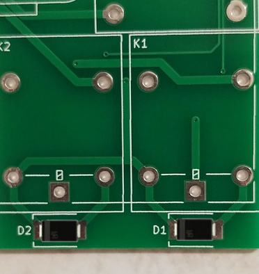
For the soldering of the diodes onto the board, is the Cathode on the left pad while the Anode on the right pad?
Looking around, I can’t find anything that only denotes one side of a diode/LED like the silkscreen in the image. ie: https://electronics.stackexchange.com/questions/210753/whats-the-standard-for-denoting-the-orientation-of-an-led-on-a-pcb
(want to make sure I solder the right way the first time)
EDIT:
After using more of my noggin, I think I figured it out. I believe now the Anode is the Left pad and Cathode is the right pad. Correct me if I am wrong but looking more at the schematic for the pcb, I realized that a 5V power comes from the pi zero to both the left pads.
Looking it up from the schematic on github this is the polarity photoshoped.
1 Like