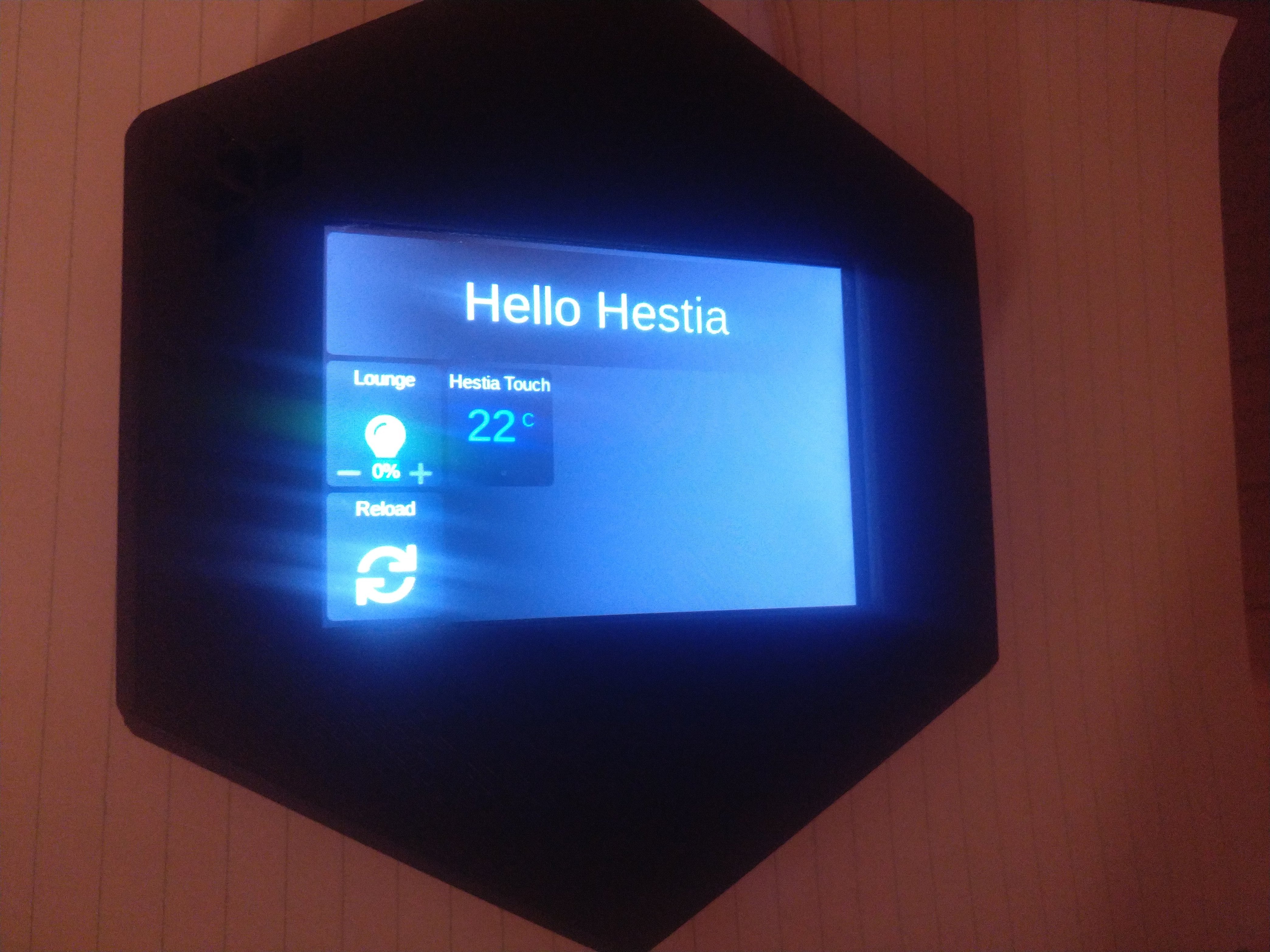
So I’ve (very belated) gotten around to setting up my Hestia Touch. It’s been sat on my desk a while
I’m going to be using it as a remote temp sensor / touchscreen for a HomeAssistant-driven setup, so these are my steps so far:
Flashed the 10.4 firmware from the New Releases thread
Mounted SD and configured my Wifi
Wire AC 240V power to L/N - nothing is connected to the H/W relays as it’s not driving a boiler
Boot up, log in via SSH
Run ~pi/scripts/update.sh
systemctl disable openhab2
Edit ~pi/scripts/openhabloader.sh to boot into the HA Dashboard instead of OpenHAB
This is all working fine . However, the onboard BME sensor is not happy:
pi@raspberrypi:~$ scripts/bme280.py
Traceback (most recent call last):
  File "scripts/bme280.py", line 173, in <module>
    main()
  File "scripts/bme280.py", line 161, in main
    (chip_id, chip_version) = readBME280ID()
  File "scripts/bme280.py", line 56, in readBME280ID
    (chip_id, chip_version) = bus.read_i2c_block_data(addr, REG_ID, 2)
IOError: [Errno 121] Remote I/O error
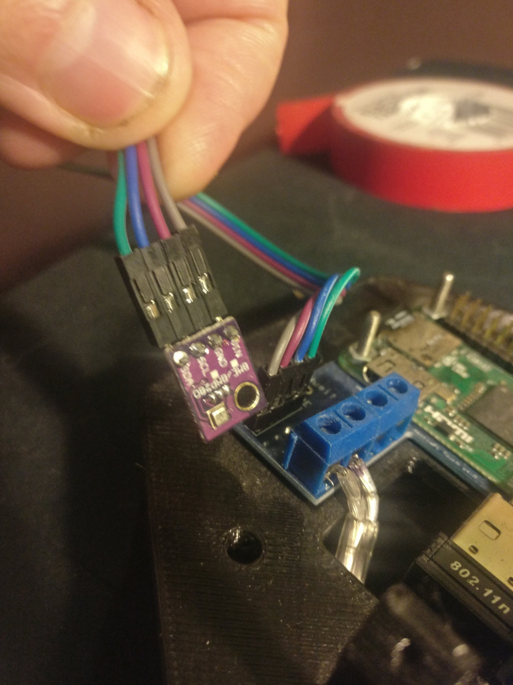
That would suggest a wiring issue, but as far as I can see, the sensor is connected tightly, nothing seems loose. Any suggestions for what to troubleshoot next, @HestiaPi?
I assume the sensor is wired Vin to Vin to the PCB, right? I know its obvious but I need to ask.
Do you see any physical damage to the sensor board? It is relatively robust.
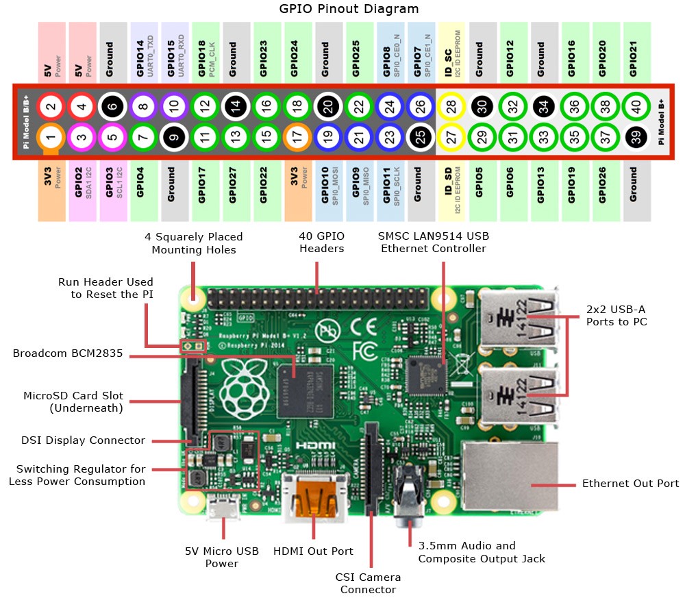
If it does not, measure voltage between Vin and GND (should be 3.3V) and check continuity between BME board and Pi pins for SDA and SCL with pins 3 (GPIO2) and 5 (GPIO3) respectively:
No, the output of i2cdetect -y 1 is entirely dashes. I do get 3.3V at the sensor, but it looks like the track to pin 3 has an issue (I get a tone from my multimeter on SCL -> pin 5, but not for SDA -> pin 3).
Are the Dupont cables soldered to the board? I was going to tug out the SDA cable and check the board had continuity, but I can’t shift it
You actually have a (very) old board as it is over a year since I sent it and a lot has changed since then.
I was getting some people pulling the dupont wires while assembling so I soldered them to be sure as removing them is not really needed at any point. With the continuity test, try to detect where it is broken. I suspect it is the soldering of the Pi on the PCB on that pin, so place one probe from one side of the PCB and the other probe on the other. Having a third hand would be handy these days…
yes
remove the 4 nuts if there is no continuity between pin 3 and pin SDA on the main PCB (not the BME board).
Hey, at least it sounds like an easy fix instead of having a broken sensor
If you haven’t already done so and if HA UI is not very picky, you should drop Chromium and use kweb or something similar like we use in the latest (not released yet) version of UI.

 . However, the onboard BME sensor is not happy:
 yes
yes