Problems running UI code on PC

I’m running the UI code on my PC, and the Heat, Cool, and Fan mode icons are not being displayed:

Any idea what the problem might be?

Also, is there a way to enable the cursor?

I’m not familiar with Vuex, so I’m doing a tutorial on that now.

I’m running the code in MS VS Code.

If you open your browser’s developer console and refresh you should get an error to point you in the right direction on what the issue is, but just guessing it may be the UI isn’t able to connect to the server. Have a look at: https://github.com/HestiaPi/hestia-touch-one-ui#run-a-local-web-server

When starting your development server, you will need to specify an environment variable that provides the thermostat’s IP address:
MQTT_SERVER=192.168.1.23 yarn serve
Replacing 192.168.1.23 with the appropriate address.

If you’re receiving a different error in the browser javascript console let me know so we can troubleshoot further.

1 Like

Thanks.
Here’s what I get in the developer’s console:
image

I don’t have openHAB running. Do I need that? What does it do?

You said:

When starting your development server, you will need to specify an environment variable that provides the thermostat’s IP address:

What is supposed to be acting as the thermostat?

Also, when I setup my environment, I ran:
yarn build
yarn serve

But I didn’t start an openHAB server. Is that the problem?

Yeap :slight_smile: the UI has no knowledge of what is happening. All the work is done in the HestiaPi instance communicating via MQTT either as localhost (run on the same system which is the standard scenario) or as a local IP.

1 Like

One thing you can do is to look at the openHAB rules code, particularly the initialization rule and see what Items get initialized on a first boot. Then look at those Items’ configurations to see which ones are linked to MQTT channels. Those are the Items that drive the LCD. Look at the MQTT Things associated with those Items to learn the topics and then you can simulate an openHAB instance by using mosquitto-pub and mosquitto-sub, or MQTT.fx or MQTTExplorer (my preferred tool) to manually publish and monitor the MQTT topics to drive the LCD by hand.

1 Like

Thanks for all of the responses. I think it would help if I understood the high-level software architecture. Is there anything that documents that? For example, what are the major software components, and where do they run? I know that the UI code runs in a Web Browser. In the real thermostat, what is the server? Is that an openHAB server running on the Pi? Are there any other major components at the level of the Client and Server?
Thanks

I’m not sure there is from a global perspective. In general the UI is it’s own project and the openHAB configuration is it’s own project and the two communicate with each other using Mosquitto/MQTT. When the UI starts up, it does so in a default mode like you showed above and waits for MQTT messages from openHAB to tell it what is going on.

From the openHAB side, commanding the Item SystemType will cause an MQTT message to be published that will tell the UI what icons to display. Commanding the Item TempUnit will cause an MQTT message to be published telling the UI whether F or C is being used. Important for you, when it receives C the UI will use one decimal place instead of just integers.

On the UI side, changes made to the setpoints generate MQTT messages which are received by openHAB which update Items and cause the logic to apply the new setpoints as appropriate.

I’ve started some Activity Diagrams to show how the v1.2 openHAB Rules interact with each other but I’ve not finished and need get them done. I can post the couple that are reasonably complete and correct if it will help, but it looks like you are mainly looking at the UI code and not openHAB code.

If you do want to run a simulated openHAB along side the UI on your Ubuntu machine, you can install it and then copy the files to the right locations (I can provide if desired). Then I’d recommend removing the Exec and GPIO bindings just to eliminate the massive amount of errors that will appear in the logs. But I don’t think that’s necessary for what you are doing, at least not yet.

What I’m not certain of and can’t look at the moment (I’ll try to remember to come back) is whether when TempUnit is F that it rounds the temp to the nearest integer or not.

1 Like

Thanks, Rich. That info is a big help. Yes, I’d love to see the Activity Diagrams. What tool are you using to create them?

I’ll take a look at everything you suggested and then figure-out my next step, but I’m thinking that I’ll probably want to setup the rest of the system to simulate the entire Thermostat, because I also have some ideas for a custom schedule and controls that I’d like to try to implement.

Draw.io so they can more easily be checked in and kept up by others.

Here are a couple of the drawings which are mostly complete and correct to give you a feel for the layout of the rules. It won’t let my attach the raw drawio file though. But It’s high on my list of priorities to get checked into the repo.


1 Like

Before I pretty this up any more, is this correct. Please pick nits :slight_smile:

Rich, thanks for the sequence diagrams. I’ll study them in more detail after I’m sure I have the high-level architecture straight.

What’s the easiest way to setup the back-end code to run on my PC? At this point in my understanding of the architecture, I’m thinking that only the openHAB Server. Is that correct?

Well, you are missing the web UI and the phone app as user inputs. The rest is more or less correct.

Apart from the openHAB server there are many bash scripts that are specific to RaspberryPi hardware, OS and architecture. Some are vital, some are optional. I don’t know of a way to run these apart from some sort of virtual environment but this is not my area really to suggest.

1 Like

Thanks for the feedback. How’s this?

1 Like

Yeap, that’s about right :+1:

1 Like

What code actually talks to the sensors and HVAC ON/OFF Controls? It doesn’t seem like that would be part of the OpenHAB Server. Are the HVAC Signals controlled by code that is executed as a result of handling Rules? What about the Sensors, what code monitors them, and what code does that monitoring code interact with?

All scripts for sensor etc are in /home/pi/scripts folder. See the wiki.
GPIO ON/OFF controls are actually triggered by the openHAB itself though.

Yes.

OH monitors the change of the output of the above scripts and rules are triggered when this happens.

1 Like

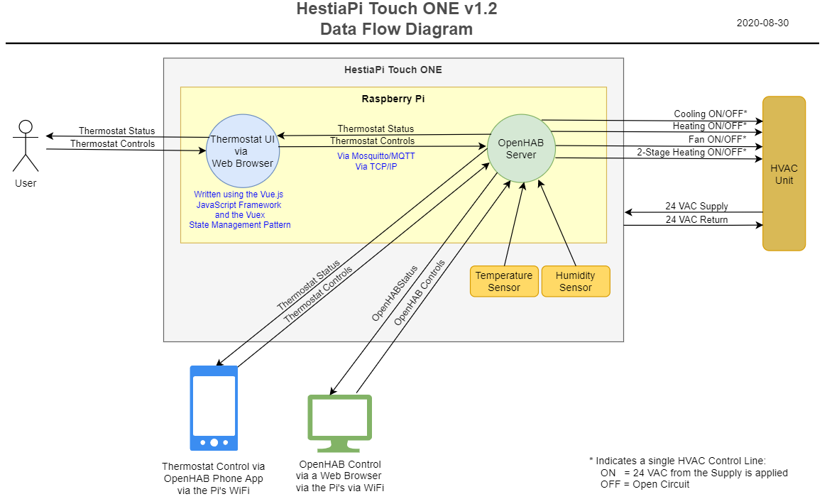
That drawing looks mostly correct for the US mode. There is an EU mode as well which removes the AC and fan and adds in the humidifier/dehumidifier and hot water controls. I can’t answer any of the details about the UI but for openHAB the behavior is controlled via JavaScript rules edited and managed through PaperUI. Communication to control devices is through the GPIO pins. The sensors are read through the Exec binding calling to a python script. And communication to the UI is through MQTT.

openHAB also serves up the web UI.

openHAB calls a Python script called bme280.py which uses the Adafruit libraries to get the sensor readings using the Exec binding.

openHAB has a GPIO binding that it uses to set the pins to high/low which triggers the relays.

Yes. The rules process the sensor readings and when anything relevant changes goes through the logic to determine whether or not to turn on or off a device. When the correct state is calculated, the rules send a command to the Item that represents the GPIO pin that controls the device. the GPIO binding then changes the state of the pin to turn on/off the relay activating/deactivating the device.

The Exec binding runs periodically and calls that bme280.py script. That updates three Items that represent the sensor readings, MyTemp, MyHumi, and MyPressure. When these Items change, the “Process Sensor Changes” rule runs and checks to see if the sensor reading has changed enough to process the change. That keeps the noise in the sensor readings from causing the rules to run unnecessarily.

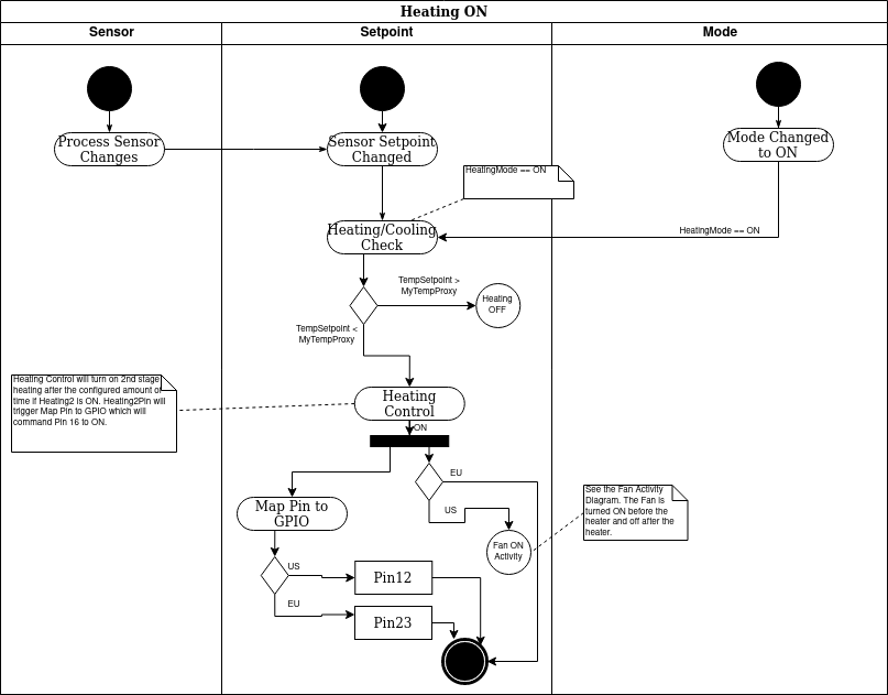
If the change is enough, the PreviousTempReading (or Humi or Pressure) Item is updated with the sensor reading. That triggers the “Sensor or Setpoint Changed” rule which looks at the sensor reading, the corresponding setpoint, and figures out which device may need to be adjusted to react to the change. Let’s follow a temperature change so this rule will send a command to “Heating Check” or “Cooling Check” if Heating or Cooling Mode is in a state where it might turn on (ON, or BOOST, or AUTO).

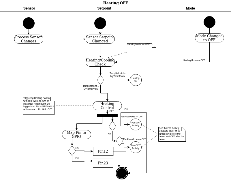
“Heating/Cooling Check” runs and looks at the setpoints, sensor readings, and modes and determines whether or not to turn on or off the heating or the cooling. It in turn sends the ON/OFF command to an Item representing the device, let’s say heating in this case which would be the HeatingCtrl Item. This triggers the “Heating Control” rule.

The “Heating Control” rule checks to see if it’s safe to turn on/off the heater, controls the turning on/off of the second stage heating, and ensures that the fan gets turned on prior to the heat and turned off after the heating is turned off. To turn on the device it sends ON command to the HeatingPin Item. This triggers the “Map Pin to GPIO” rule which sends the ON command to the Item representing the specific GPIO pin that is attached to the correct relay.

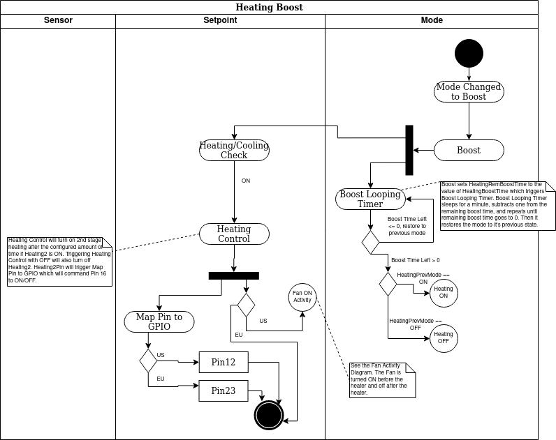
This seems a little complex but one of my driving motivators was to avoid duplicated code where possible. Therefore, if one decides to run a boost for 10 minutes of the heater, the same “Heater/Cooling Check” rule gets called as gets called when the temperature changes. Adding new sensors and behaviors is easier now as well as all the code is in one place. So, for example, if one were to have second stage cooling instead of heating, the logic for second stage heating could be moved to the “Cooling Control” and no matter how cooling is activated the second stage will activate. If another relay were added to control another device (lets say you have a house fan not connected to the HVAC blower) you only need add the Items and add them to the right Groups and add a Check and Control rule to run it and you can leave much of the rest of the logic unchanged. So if you want to control this fan using a boost mode, you don’t actually have to copy that logic and reimplement it. Instead you just need to add the right Items to the right Groups.

2 Likes

Thanks! I’ll update the figure to indicate that it is for the US Model. Next I’d like to develop the next level down DFD, and the info you provided above will be a big help with that. If I finish these figures, maybe I can add it to the code base.

I would like to get a completely simulated HestiaPi setup to run on my PC. Can you tell me where to start to setup openHAB on a Ubuntu machine?