I bought a HestiaPi Touch v6 in spring 2019 (as much to support the project - many thanks for all the work!) and I’ve got it working wirelessly, so I thought I’d share in case it helped anyone else. I’ve since replicated the process with a spare Pi Zero W, which is what I’m sharing.
The result is a simple (optionally screenless) HestiaPi wirelessly controlling my boiler over MQTT (a bit like in this instructional: HestiaPi + ESP = – HestiaPi).
It’s relatively simple to do, so some here might regard it as obvious, but newbs like me might not know some of the ins and outs which is why I’m sharing (and why I’m stating the obvious at times). My project included work with mains wiring inside the boiler, please do not try this if you are not competent and legally qualified, seek professional advice.
My setup at home (UK) is a 15 year old natural gas combi-boiler (vaillant turbomax) running on a mechanical time clock, without a thermostat (or separate hot water). I don’t have thermostat wires anywhere in the house (so my HestiaPi v6 board with relays on didn’t really help, I might give it to an interested friend) and I didn’t want to install a wired thermostat.
I used:
- Pi Zero W v1.1 with a GPIO header (could solder directly).
- A BME280 with a header & connection wires (I bought the same board as supplied with my Hestia v6: https://www.ebay.co.uk/itm/253107395109).
- A spare microSD.
- A Sonoff Basic (plus connection wire and a waterproof case cause it’s near the kitchen sink).
This is how I did it:
- Flash the SD card
I downloaded the HestiaPi ONE (v1.1) image & flashed it to a microSD using BalenaEtcher (MacOS).
- Set up the Pi hardware
Using a Pi Zero W v1.1, I inserted the SD, and connected the BME280 to the correct pins on the Pi (the 280’s board is marked Vin, Gnd, SCL and SDA - I checked the BME280’s hardware setup here (there’s no need to configure it, HestiaPi does that for you): https://www.raspberrypi-spy.co.uk/2016/07/using-bme280-i2c-temperature-pressure-sensor-in-python/
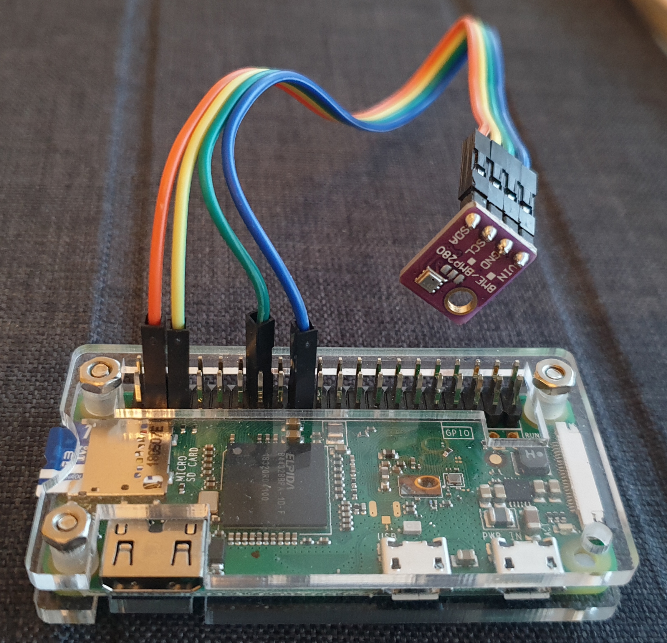
Here’s one I made earlier (I’ve used other 3.3v/Gnd pins so it’s easier to see).
- Power up the Pi
I had a mini HDMI connector, so I plugged the Zero into a monitor to keep and eye on the set up progress (this isn’t necessary). I’m not 100% sure which 3.5" touch screens are compatible, but it works without. This stage is well covered in the docs, it reboots several times while it configures, until eventually it offers a HESTIAPI wifi access point you can connect to and add network settings at http://192.168.4.1. I set up a static IP address for the Pi in my router’s configuration page for later, then followed http://<HestiaPi IP address>:8080 on my laptop to go to OpenHab’s web interface. Once the UI had set up I took a look around the Basic UI, and changed the settings to suit my setup.
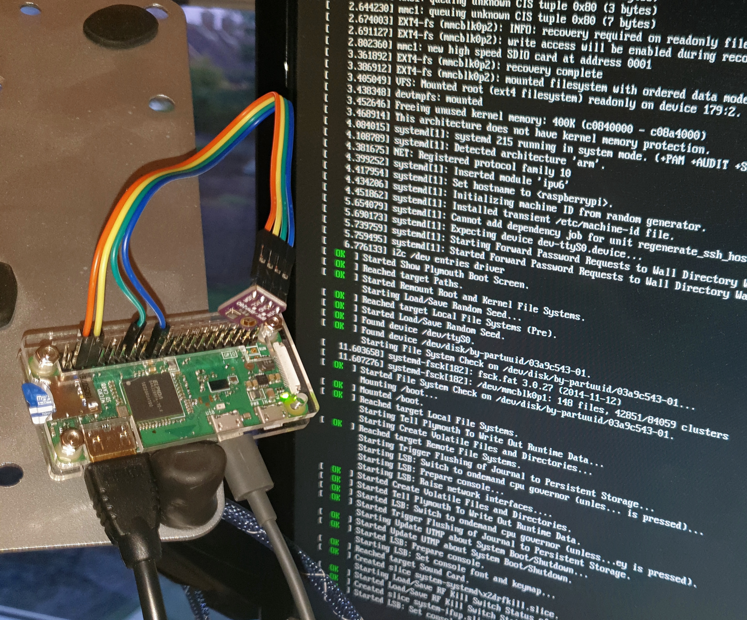
My very basic HestiaPi Zero W with the BME280 booting up and configuring itself.
- Exploring the Pi’s MQTT output - follow the link to learn more about MQTT
This is where my install gets more customised.
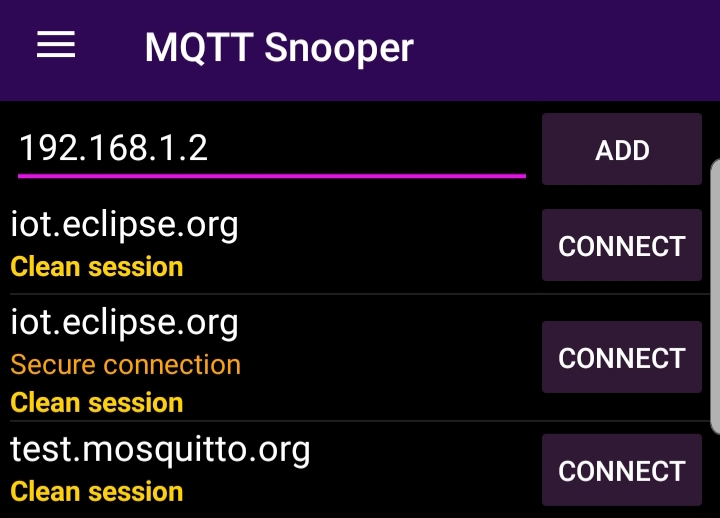
I installed MQTT Snooper for Android (others are available), added my Pi’s IP under Host in the menu, e.g. 192.168.1.2, clicked “Add” and then click “Connect”:
Then under Topic, I typed # (a wildcard) tapped Add, and tapped On to subscribe,

Then clicked In() in the menu. Before long the app starts to receive the MQTT messages published by the HestiaPi.
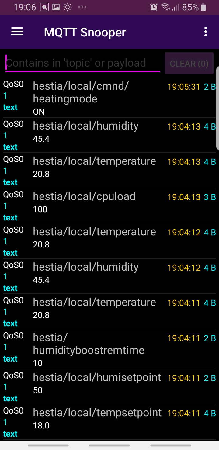
(this takes a while, because the HestiaPi One software keeps setting up, but eventually it will start reading temperature and functioning). If you set the heating to Auto in OpenHab and change the Temperature Setpoint above/below the sensed Temperature, so that the thermostat would turn the boiler on and off, you’ll notice a lot of MQTT messages like
hestia/local/tempsetpoint
18.0
These messages are the HestiaPi broadcasting MQTT messages to any devices on the network and listening, regarding its status and actions. When the HestiaPi calls for the heating to be turned on, the wired HestiaPi board turns relays on and issues an MQTT command:
hestia/local/cmnd/heatingstate/POWER
ON
This command can directly turn on the boiler wirelessly, if another compatible wifi device is connected to receive it.
- Configuring the boiler’s remote controller
I took a Sonoff Basic flashed with Tasmota as the HestiaPi blog also describes. If you don’t fancy flashing your own, they’re commonly available pre-flashed on ebay though I’ve not bought one and can’t speak for their quality.
To configure the sonoff I wired it to a mains flex/plug to supply power (though I could have wired it as in step 6 if I was more confident it would work), connected to its wifi configuration page, and set up its MQTT Configuration as described in the blog, using the HestiaPi’s static IP address for the MQTT Host, and:
Topic = %topic% (tasmota):
hestia/local
And
Full Topic (%prefix%/%topic%/):
%topic%/%prefix%/heatingstate
These configurations connect the Sonoff Basic to my WiFi, connects it to my HestiaPi as the MQTT host, and subscribes it to those command messages the HestiaPi issues on the “heatingstate” topic. When the temperature gets too cold, or the Boost button is pressed on the OpenHab UI, the HestiaPi issues the command
hestia/local/cmnd/heatingstate/POWER
ON
That command (cmnd) is received by the Sonoff because it is subscribed, and so the Sonoff turns its relay on (I wired an extension socket to it to test it with a table lamp, but you can hear the relay click and see the LED turn on and off too). All that remained was to connect to my boiler.
CAUTION - Please seek the advice of someone qualified and competent before you proceed if you plan to do something similar to my next step - do not attempt to copy what I have done, consequences to you (or others) of doing so may include, but are not limited to, damage to property, serious injury and death. The following is not advice or guidance. Stop & think.
- Wiring the remote to the boiler - CAUTION
I turned my boiler off, disconnected the power. The circuit board of my boiler looks like this. Terminals 3 and 5 are Live (240v) and Neutral respectively. If terminal 3 is joined to terminal 4, and the time clock control is on, that triggers the boiler to fire and the heating powers on. I decided to use the Sonoff to switch connection between 3 & 4 to add remote control.
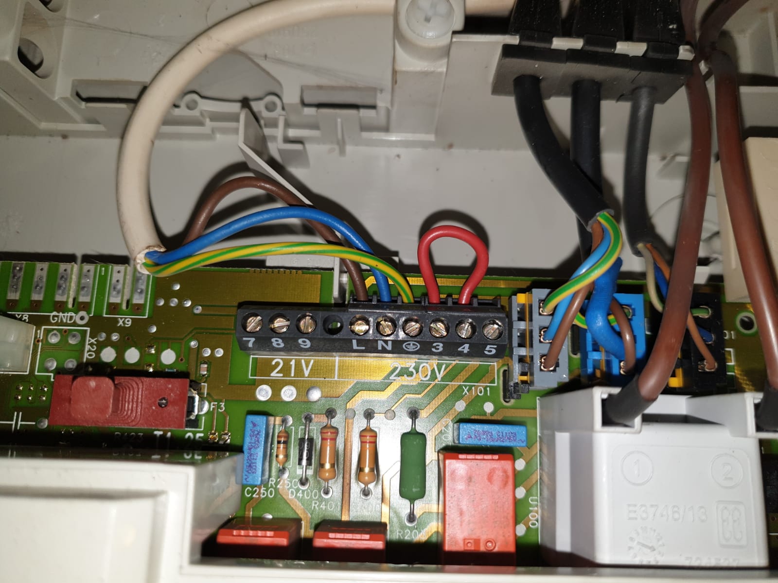
I wired the Sonoff connecting terminal 3(L) & 5(N) to the L and N input terminals, to power the device, and connected terminal 4 to the L output, which is switched by the sonoff’s relay:

The extra wires on the left in the waterproof box are disconnected, I was using them when I was testing the setup, but they will be removed. The Sonoff was connected to the boiler with a piece of mains flex, the brown sheathed earth wire used for the switched live (marked red), and the device insulated in a IP66 rated enclosure (which turned out to be slightly too small).
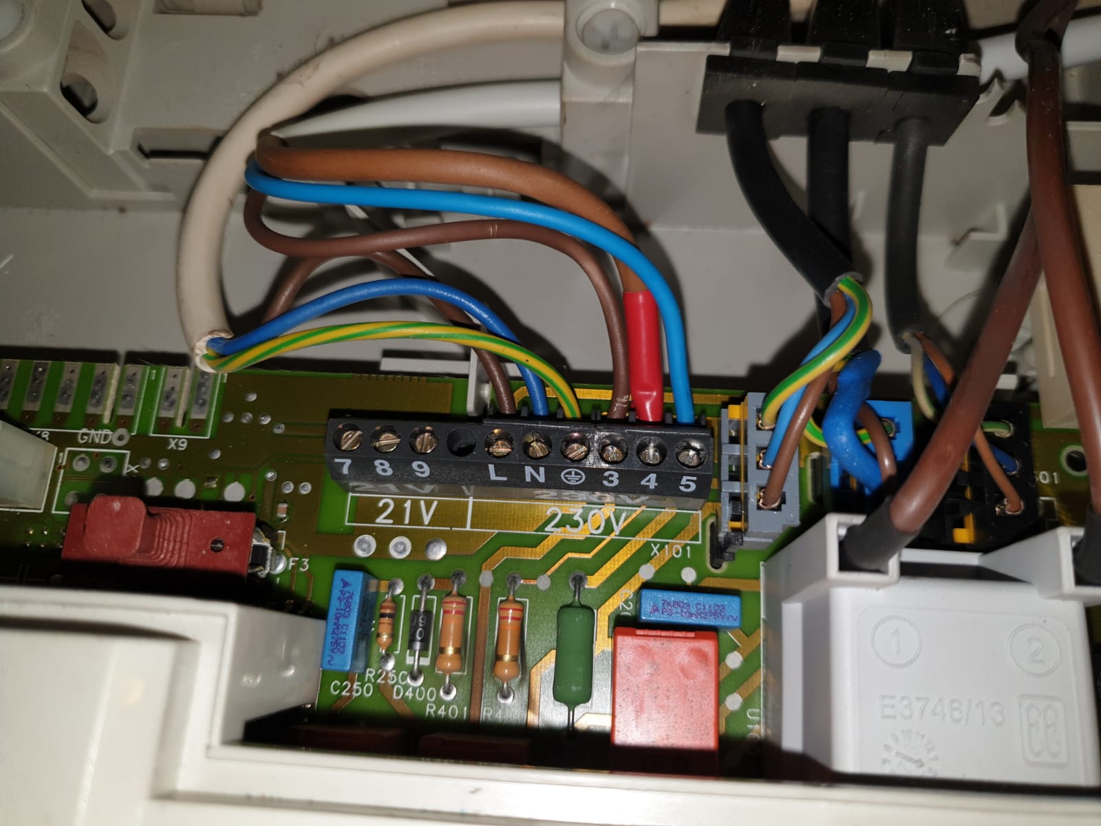
The other end of the flex was connected to the control board as described above.
With the boiler secured, and then powered up, the Sonoff came online, and once the HestiaPi had started up (can take a long time even after initialisation, I’ve found), the boiler can be controlled using the OpenHab interface.
Conclusion
That’s the account of my minimalist Hestia Pi setup. I need to learn about Last Will and Testament (LWT) in MQTT, I think it can set a default state if the boiler becomes disconnected from WiFi or the HestiaPi goes down. I want to add screen dimming too (and a screen!), but that’s for another day. My boiler still has a mechanical time clock, and I’m still using it AND the thermostat - I’ve not found a way to add timings in OpenHAB.
Thanks for reading. Feel free to leave comments, questions, ideas, etc. Hopefully I’ve not done anything daft.
Jon