“Ask a professional to fix HestiaPi to the wall and follow the wiring below, according to your model.”
Hi guys, I assume step 1 is for legal purposes, but I really didn’t anticipate needing/wanting to hire a professional to install this device, not to mention my HVAC service provider will likely balk at installing this device into my HVAC system.
I can tinker with linux and was able to follow the directions that came with my nest thermostat. I had assumed installing the hestiapi would be somewhat similar to installing a nest: connect the wires in the correct places type of thing. But I don’t see where the wires coming out of my wall plug into the hestiapi. And I couldn’t find any online instructions except “complete wiring according to your model instructions.”
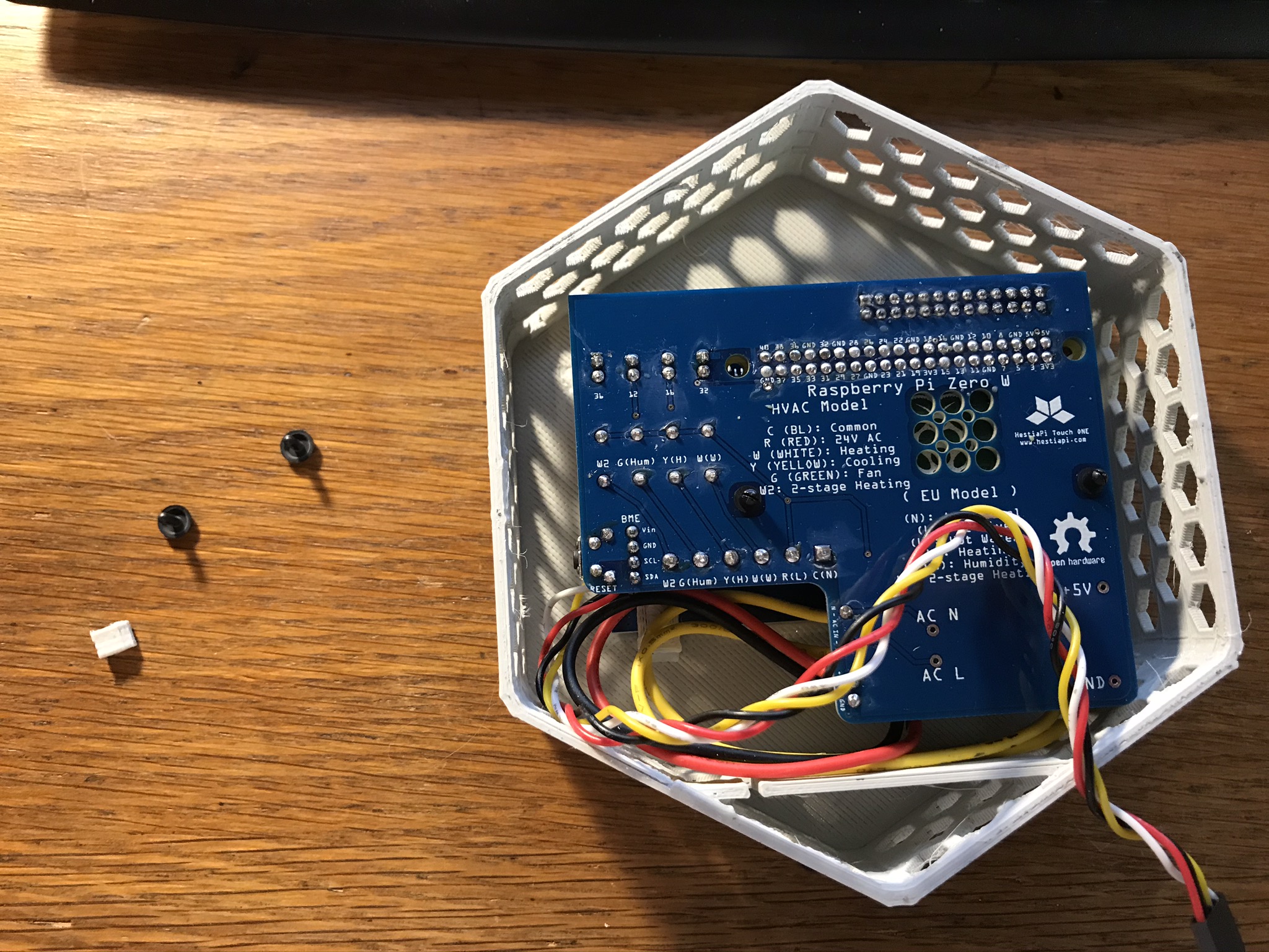
Behind the screen on the bottom right of the circuit board there are six blue screw down ports (I don’t know the proper name). These are where the wires will be connected. Each one is labeled as to what it corresponds to in the wiring diagram that came with the unit.
I went from a Nest to a HestiaPi too. What I did was:
Turn off the furnace’s circuit breaker. At best you’ll blow a fuse, at worst you’ll ruin the furnace’s control board if you fail to do this step. Luckily I just blew a fuse and the local auto parts store had replacements.
Remove the Nest body.
Take a picture of how the Nest is wired. Make the picture clear enough that you can see the label on the “button” and the color of the wire going into that button.
Remove the wires one by one.
Remove the Nest mounting bracket.
Attache the circuit board to the back plate for the HestiaPi (without the LCD)
feed the wires through the hole at the bottom of the back plate and attach the unit to the wall.
attach the wires to those blue screw down ports, tighten the screw well. You might need a magnifying glass to read the teeny tiny labels telling you which port corresponds with which function. IIRC the labels are the same as were on the Nest (C, H, etc.).
Slide the LCD into the top cover and carefully align the LCD pins with the pins on the circuit board. If you’re off by one it could fry the LCD’s touch sensors.
Turn back on the power.
This is just what I did, and I’m going from memory.
thanks for the response Rich! I’ll add that I was of the people who received a damaged product initially and I had to send it back for a replacement that was apparently packaged nicer. That experience has made me try to handle this quite gingerly. Nevertheless I still have a couple pieces free floating that I assume aren’t critical. But anyway, I suspected there might be blue screen down ports but I can’t see them. I’m looking at the back of the device. The board, with its attached LCD, seems firmly attached to the body. I tried to gently gently gently take it out but no luck and I’m worried about breaking it.
Hold the white case with one hand and pull the blue PCB to the opposite direction. There is a 26 pins header connected at the top which adds some force needed. That PCB should have stayed with the other part of the case that goes to the wall. You can replace those plastic black rivets with M2.5 nuts and bolts if you wish as indeed have been weak.