U.S. 24V PCB with additional relays

On a previous post I mentioned needing a 5-wire setup for my HVAC as well as 24v. A friend helped my come up with a compatible board design that still fits in the original case. I know at this point HestiaPi’s funding campaign has them coming out with a board that supports common wire but I wanted support for extra wires and wanted it sooner so here’s the design if anybody cares to use it or offer some feedback.

Overview:

  • 24VAC (common wire) support
  • Support for 7 wires
  • Extra current protection
  • Larger ground plane
  • Should produce less waste heat

Download link

I haven’t tested the board yet but have sent it off to be printed. I will post an update once I’ve assembled and tested.

4 Likes

Just giving an update, the board has been running for some weeks no problem. Sorry I meant to post pics much sooner:


Today I’ve switched from openhab to @janbonne’s iothermostat image based on Arch Linux and although it needs further tweaking to support all the additional US wires, the speed and responsiveness has been worth it (video back on the testbench: link).

One slight revision to the board was to add labels to the screw terminals. My layout based on how I’ve programmed it:

21=G
20=W
16=Y
18=Y2
24=E
12=O

Once I have a US version of iothermostat working I will push up a git repo in case anyone is interested in using it with their own thermostat. The pins will be easily configurable so you can enable or disable what your unit has (for instance if you don’t have 2nd stage cooling then Y2 can stay permanently disabled.)

Great work @jay!
We’re working on optimisation too here before sending the crowdfunding orders. Dumping HABPanel UI and Chromium for websockets MQTT, native HTML, Javascript, CSS and kweb browser in kiosk mode. Looking very promising…

@jay,

I also have been working on a compatible setup for my system (5 wire) and have gone through a few designs that haven’t panned out. I like your design and I think I’m going to try it out. At the best, I am a novice so I’m sure I’ll have questions down the road here. Thanks for the contribution to the project and I too would like something sooner than later. Any pointers before moving forward?

FJZ

@fjonnyzoom thanks for your interest. If you can wait a few days, I can upload a new version that has proper labels for the relay pinout as well as some other tweaks to make assembly easier. The original iteration uses many surface mount parts that can be a challenge for a novice solderer.
Another challenge is at the moment is the software isn’t all there. I am using a custom version of the iothermostat image that adds support for the additional pins but the interface was designed for EU units and therefore uses celsius and has no button to switch to cooling. I may develop a US version of the interface myself or help someone else interested in having one but currently I am devoting my spare time to developing an interface for the official HestiaPi image that will also support the additional pins. So it will be some days before I have a ready image to complement the hardware.

2 Likes

Here is a quick peek of the settings section of the backend:
image

Power: offers restart and shutdown
2nd stage: controls the parameters of the the 2-stage furnace scenario

More will be added in the following days, like changing timezone and enabling remote phone notifications, before releasing the crowdfunding campaign image.
All features shown will be available in the phone App and the browser view. For simplicity, one off settings (F/C, HVAC/Generic) will not be available (read take space) on the LCD.

1 Like

Thanks for the update! I did already order your version of the board and have previously gone through two others but I’m having a good time learning a bunch of new things. I’ll setup the board the best I can and try it out. I’d like to help contribute to some of these projects but again, I am pretty new to these things and wrapping my head around some of these posts and forums is difficult especially if you’re new. I’ll keep an eye out for your updated software and in the meantime I’ll add my experience with the project as well.

@fjonnyzoom cool. Let me know if you have any issues. Worst case I also have a few spare boards I’m going to assemble when my schedule is less hectic.

@jay will do. I’m getting them in on Monday and assembling the list of parts.

@jay Just got those boards in with a solder template which I won’t need but wanted to try and use it for experience. Did you have a parts list for this? I was looking around for it but could find one for your board. Thanks again for your effort!

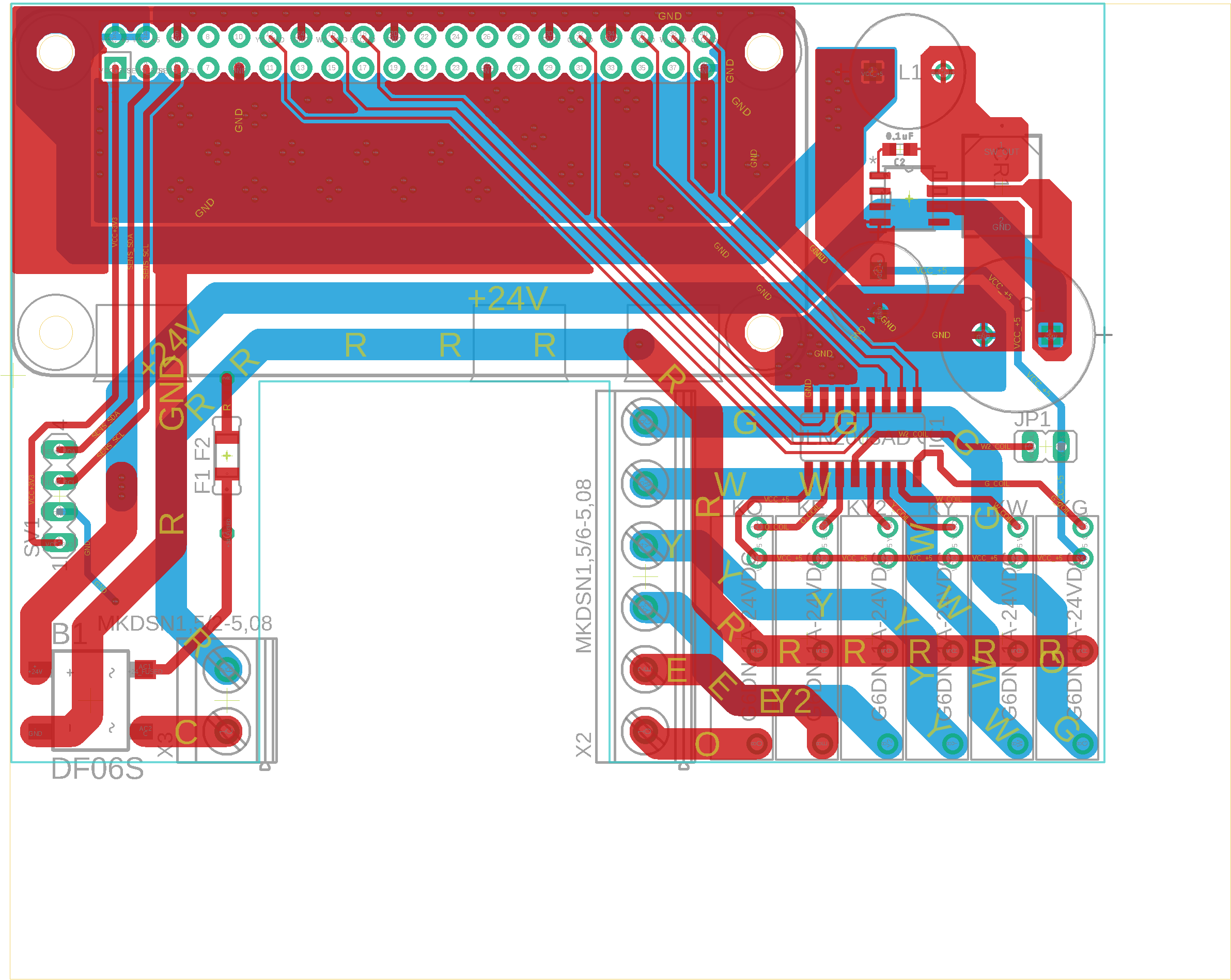
I’m the actual designer of this board and here’s a preliminary bom
https://pastebin.com/vMXirDGN thats a csv of the digikey bom
this link should work if you have a digikey account,
https://www.digikey.com/BOM/Create/CreateSharedBom?bomId=8012033

the 4 two position terminals can be replaced with a 2 position and a 6 position it’s $.20 cheaper for less than 3 boards.

a few notes for assembly if you’re doing it with an iron, tiny capacitor first, voltage reg second, diode third
if doing it with hot air just paste it up and reflow

the polyfuse also has pads bypassing it for a fusible resistor, or any other through hole protection device you want or just bridge the pads if you’re brave.

Known bugs.
there is zero interference or overvoltage protection in the bom
you can put an x capacitor across the ac input if you have interference issues, there are holes provided
if you want you can put a varistor across the provided vr1 pads or something fancier for overvoltage handling
it could really use a common mode choke.
the idea was to use a small premade line filter external to the board if it becomes an issue.

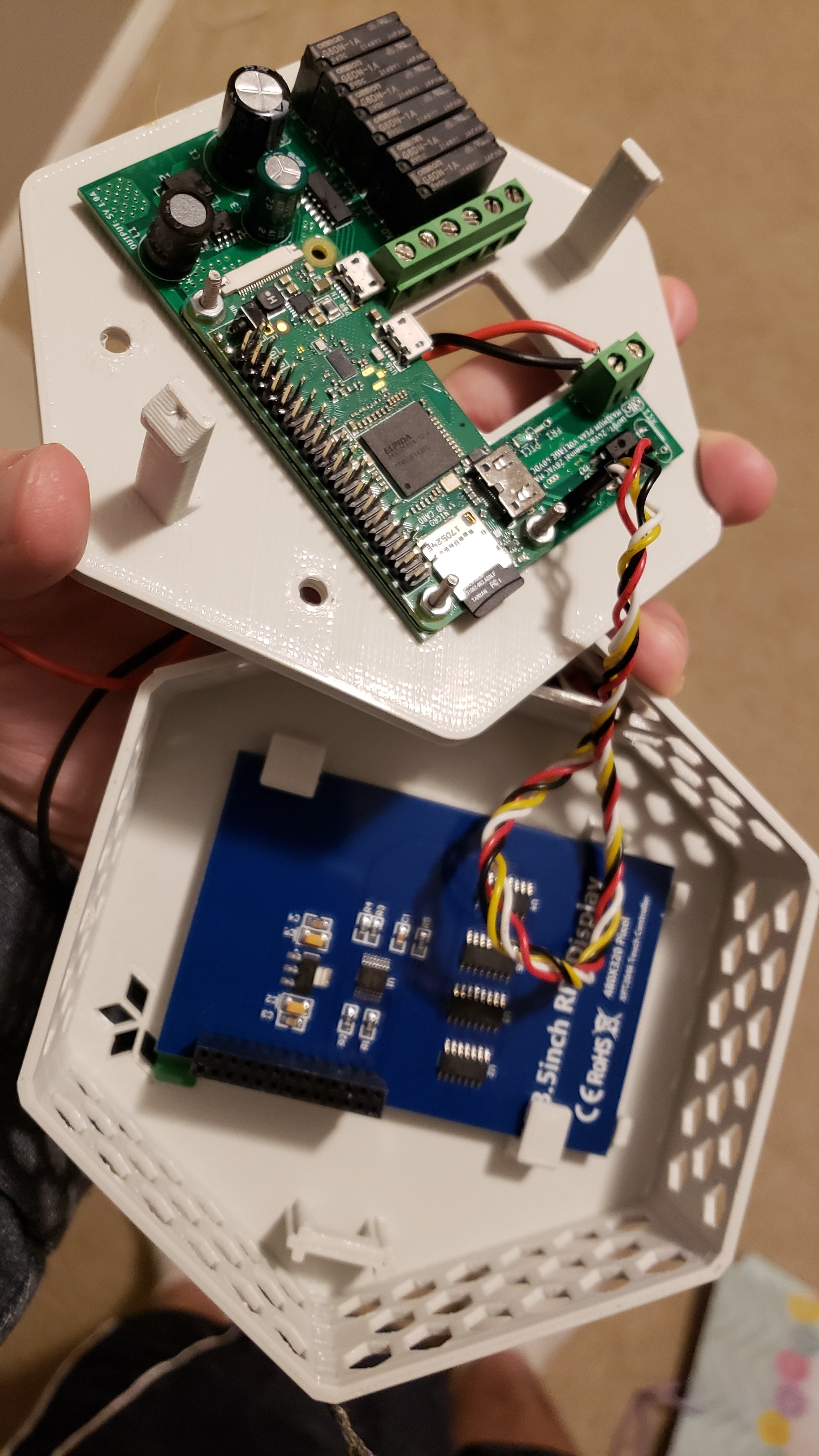
I wouldn’t run any audio off this design as there’s some regulator noise on everything the pi doesn’t seem to care and neither does the touchscreen.

Some notes about capacitor selection.
That particular C3 is not exactly what i used in my working boards but it’s a close approximation of the chinese one i pulled off a tv power supply just testing values.

C2 seems to work best as either a 68uF-560uF poly cap in various voltage ratings or as a 16v >=470uf electrolytic with a ceramic cap on the underside, a ceramic capacitor alone of sufficient value will just cause problems.

In a week or two i’ll have a really solid combination characterized i just don’t have a good programmable load to test with.

Troubleshooting the regulator.
Originally i got all kinds of oscillations on the power supply when the pi drew too much current. if you have issues try using a motherboard capacitor of higher value or pretty much any low esr cap you can find in place of C2 or try any 50v higher esr capacitor at C3.

it seems to work fine to power a pi3A or a pi zero but it still needs more testing.

1 Like

@oddbondboris Thanks for the update, great job on this!

@oddbondboris The link didn’t point to the BOM at DigiKey. Is there anywhere else I could grab that?

edited the post to include a proper bom link and a pastebin of the csv.
you need a digikey account to use the link but it should work on anyone’s account

@oddbondboris Awesome, thanks so much for the edit and update!

@jay Have in all of my components. Do you have a pinout for this board?

@fjonnyzoom do you mean the hvac pinout from the first post? They are listed from the top screw terminal to the bottom (left relay to right).

If you want to test yourself, set the multimeter to continuity and match the physical RPI pin to the BCM pin number used in software. https://pinout.xyz/#
The BCM pin can be used to trigger the relay from the command line:

echo "16" > /sys/class/gpio/export
echo "out" > /sys/class/gpio/gpio16/direction
echo "0" > /sys/class/gpio/gpio16/value
echo "1" > /sys/class/gpio/gpio16/value

@jay I was looking for the pcb part layout but I figured it out and now have to make sure I keep my parts oriented correctly. I assembled the first one and had something not right. Was there a version of openhab you were using with this board?

I am currently using a beta version of the official hestiapi image. I’ll direct message you a link as it’s a large image and the officially released version of the hestiapi image should be out soon.

Another update: The hardware source can be found in a GitHub repo.

@jay I’m having issues with the new software, I can’t seem to install the original image for the board I built.