Hi All and esp the person that designed the pcb`s.
I have been doodling about with Sprint Layout v6 (the easiest pcb software to use I have found) to make a single sided pcb that will control 1 relay so that I could turn it into a electronic thermostat (room stat) that controls my kerosene combi boiler heating. it is a simple open or closed relay. no mains voltage, no active voltage, just an open (heating off) or closed (heating on) switch (relay).
Nice and easy and will go happy with my customised build of HestiaPi but I am no electronic engineer and what looks right to me might be a bomb just waiting to explode taking my combi boiler and house along with it…
I need the layout checked and fixed if it is wrong or help sorting it if possible. Do the BME data lines have to be the same exact length ?? what way does the diode need to be ?? etc etc.
Thanks for reading and helping if you can
Sirhc
p.s once I find out how to export gerber and drill etc I will attach to this post or email them to the pcb wizard.
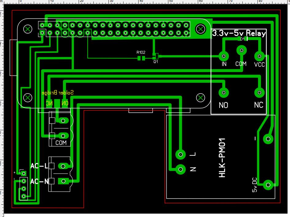
Please share a photo of the schematic and PCB tracks here in the forum for everybody to comment on. A simple Print Screen would be enough I guess.
As we usually say with these things, “if you are not feeling comfortable with something don’t just try it” especially if an expensive/important machine is at risk.
The BME data lines (and 99% of any PCB line) can be of different length.
All components are placed on the top side except R102, Q1 and D1 which are displayed mirrored in the picture
A few remarks:
You could use the “via” to save some traces
R102 should be 1.2KΩ
The little line shown to the right of the diode below the “R” going to Vcc shows the polarity of the diode. Place the diode matching the line on the component.
You can pre-connect the expected functionality of the 2 (out of 3) solder bridge points
You can move the AC terminal block next to the power supply (to the right) and if you do that you can move the other terminal block of the relay too because as you can see all the 5 lines travel across the board to the other side for no apparent reason anymore. Please note that you may block the Pi’s USB so make sure you have a Zero W or you will not be able to connect a WiFi module to a non-W Zero.
If you plan on soldering the BME sensor directly (without wires) on the PCB, the direction of the contacts (which are the opposite from the original HestiaPi’s PCB) will force you to have the sensor facing the wall 1cm off it making very questionable readings :). Consider swapping them back around.
Please ask any questions NOW and not after you send your PCB for fabrication
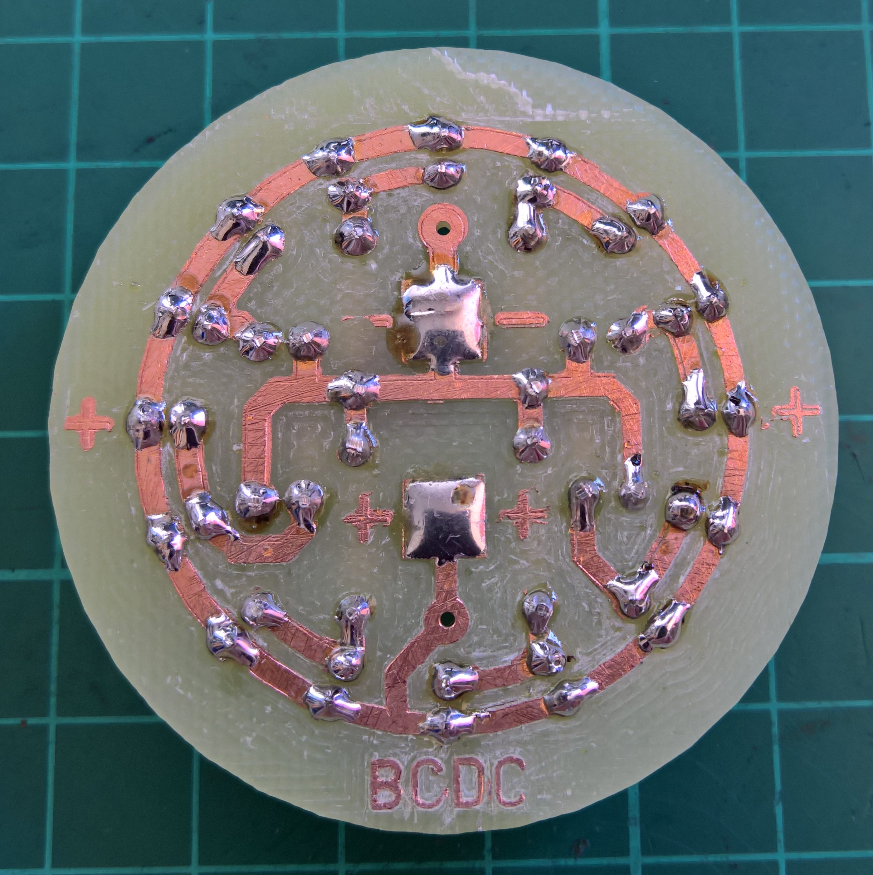
I plan on making the pcb myself (isolation track cutting, copper removal and hole drilling on a small cnc machine) that I have access to. I have used it a few times and made a few small boards for use in desk lamps so I am getting used to trying to make the gerbers and excelon drill files then turn them into cnc path files to cut on the mini cnc machine. I started with coppercam and after a week or so thought I had it nailed until it wanted $80 to save the files… pass, then I found Flatcam and after another week I had a full set of files ready to run on the cnc. I am now the proud owner of 3 sparkling jewel desk lamps (a modern version of the old lava lamp) that run at 5v 500ma so costs pennies to run. Now that I have a good idea of what to do I want to move on with this project.
I have on order double sided copper clad FR4 so I might just wait until it arrives before I redo the board layout.