@HestiaPi Is there source files available or the 3D printed case? I can only find the exported .stl files in the repo, but not the original model from which the case was exported.
Try that:
@hestia_hacker I was working on recreating the case in openscad, because of two problems I am having.
- Unless the screen is in exactly the correct place, causes touch not to work.
- my screen is a little smaller than what must have originally been used, so my screen can move around so was going to make that adjustable
I’ve recreated the case in FreeCAD to be 4mm taller (that’s the thickness of the backplate) because of the problems people have been reporting with the tolerances being too tight. In my experience, if all the pins on the back of the HestiaPi PCB are trimmed down as far as possible, it works, but if the tails are left in tact, it’s just a little bit too short.
My screens have all been a really tight fit between the LCD tabs and the front shell. It fits and it’s very snug. So if yours is flopping around in there, it seems very reasonable to make it be variable to accommodate different screen thicknesses. It’s also possible that different 3D printers and different print settings also affect how tightly or loosely the screen fits. ![]()
My FreeCAD skills are not yet to the level where I can just make the case height, and screen thickness nice little variables that can be easily changed, but I can go into the sketch and change them without much trouble. I’m probably only a small step from just making the sketch constraints be a variable, but I am still one step away.
I haven’t posted the model here because I haven’t printed it out yet to verify that everything was faithfully recreated (other than the case height). To be clear, I say “height” because the model is laid out with the case’s shell facing down (for printing), but it’s the distance from the wall to the front when the thermostat is installed.
Also, changing the case height means the requirements for the extra long headers might change. That will likely motivate me to find the limits of all these tolerances and document them. Things like:
- What’s the minimum distance the pin need to be pushed into the LCD’s female headers to function?
- What’s the maximum depth it can be pushed in?
- Do we care about the pin length, mating length, tail length, or some combination of these?
- Which of these tolerances change when the case height changes?
- Do any of them change if the LCD thickness changes?
- Do different LCD panels have different tolerances?
- etc.
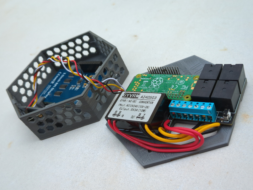
I have now gone through a few iterations of printing and making adjustments to the model and I am now getting reliable results.
It fits both the original board and the one that uses the clicky relays without changing out the extra long headers for the LCD screen.
The thickness of the case and the thickness of the LCD screen are easily adjustable, but all my components are the same size, so I haven’t done much testing with changing that and then printing. The model looks good after changing them though.
I will submit a merge request to the appropriate git repo.
1 Like
Do you use support for the screen hooks?
Yes, but no supports anywhere else.
Correct. Maybe various support settings and materials cause the LCD issues you experienced
I haven’t had any issues with the LCD screen fitting on anything I built, but I saw someone else on the forum here mention they had a different model screen that was slightly thicker.
@zenga’s issue was with the shell walls not being tall enough, or the LCD header pins not being short enough. Their LCD worked fine when it was in the shell as long ad the shell was detached from the case.
I am now fully assembling units to test for this issue before shipping them (rather than testing it with the case open).
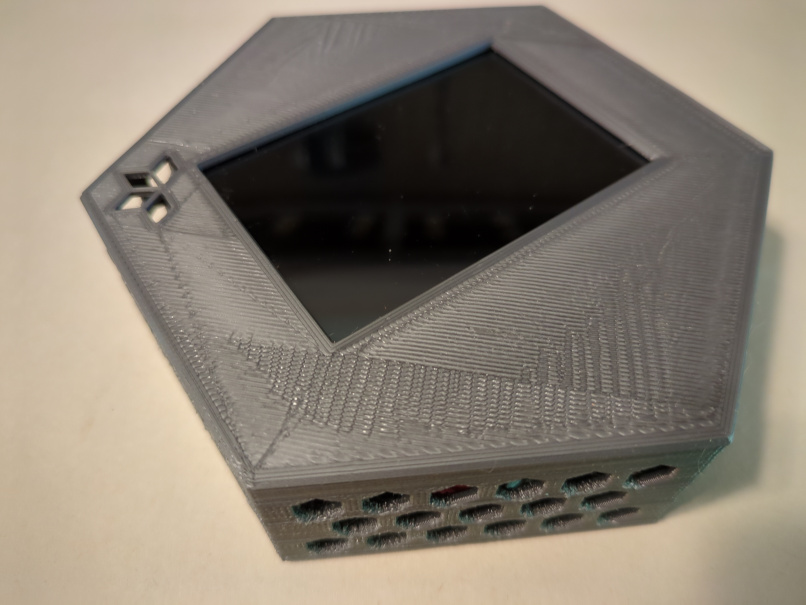
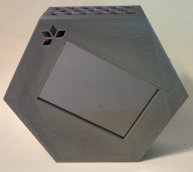
I finally got around to making that pull request.
In case people are curious to see it, it basically just looks like the existing case that you know and love. But here are some pictures to, um, I guess see what it looks like when it’s printed out in grey instead of black or white. (because grey is what I had handy at the time)
2 Likes
I’d like to try and design a case for Hestia. Is the vent area calculated for a specific air flow, or was it made this open just to be sure that the case was ventilated enough?
Also, someone mentioned having issues with the touch screen if the case was overlapped too much. Could you tell me what overlap you found to work best?
Thanks!
It was made to get the internal temperature sensor get the least error of the room temperature outside. Please note that it is placed in the bottom of the case in a separate compartment for that reason.
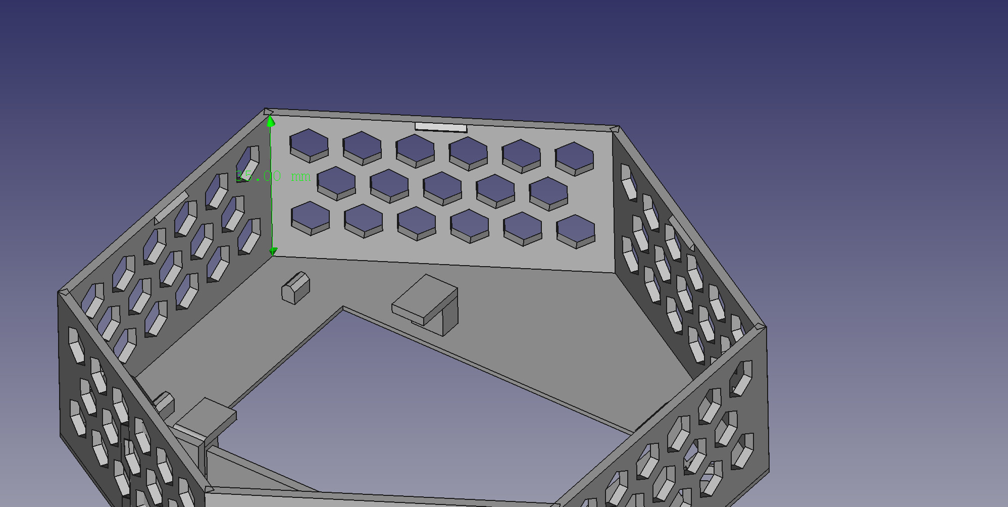
The exact size depends on what length of headers are purchased, how long the tails are on the back of the board, whether there’s a US power supply in there, and whether it’s the silent (solid state) relays or the clicky ones (traditional relays).
Having said that, it looks like 35 mm between the back of the PCB to the front face of the screen. To illustrate this, here’s a picture of the CAD model:
I’m continuing to work on little refinements in the stock case to get them to print out perfectly every time. I hope to get as close to a universal fit as possible with components that remain available for years to come.
This topic was automatically closed 91 days after the last reply. New replies are no longer allowed.