Hello,
I’ve been testing and tweaking a Hestiapi Touch for about 4 months now. I like the project but some things caught my attention.
First, I found the original linux distro and interface were incredibly slow so I installed Arch Arm linux on it (yes I am an Arch fan)
I figured I can go with a custom webinterface and python code, ditching the way too heavy java and OpenHAB. Right now my little system is very fast and all sensors etc work fine but I still have work to do.
My thoughts on some specific points:
-
The screen is touching the bevel when I push the back ‘Wall’ plate in all the way. The screen then recognizes the bevel as a touch event happening all the time and it becomes unusable.
-
Screen is not locking well in the bevel (grips too small and too short)
-
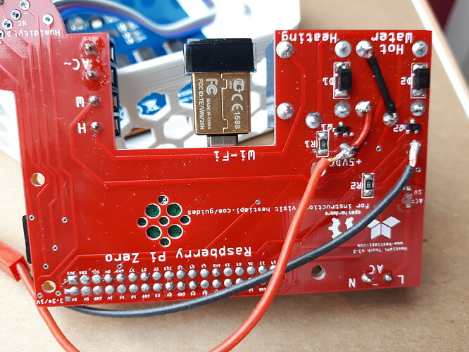
AC lines on the PCB are not isolated. Possible shock hazard here.
-
I am not an expert on this area, but the AC (230V) lines on PCB seem very close to DC lines.
-
My heating system requires OpenTherm/eBus (low voltage) for continuous modulation or simply open/closed loop for on/off modulation, and will get fried with 230V AC on the modulation port. I’ve bypassed the transformer by connecting a standard 5VDC USB power supply, which works fine and is safe. I haven’t done inquiries yet but I suspect that many European systems use low voltage or open/closed loop control. Anyway, a 5VDC USB powered version would be really good in my humble opinion (save one component?).
-
The resistive touch screen seems to not have all capabilities supported by the official drivers. Is it an unbranded version of an official Raspberry Pi screen? It seems to do it’s job though.
I hope my feedback is of value to you. Will keep you posted about my development.
Cheers,
Jan Bonne

