Hestia Touch one Pi3B

Hi!

I’ve seen many post of people looking into using a Pi3B+ instead of the zero.
Since its almost impossible to get a PiZero (at good price) and the fact that it’s not possible to get the pcb from the shop i decided to make this work with what i have in hands.

Before we got further i’m planning on using this for my RV wich work differently that the initial projet.
The RV furnace / AC / Fan work simply by sending a ground throught specific pins.
So i do not need to provide power but simply close the loop with the relay.

Here is the hardware i’m using:

PI 3 B+

TFT LCD 3,5" 480 x 320 XPT2046

Hbbebdgg GY-BME280

I’m using the already built image:
hestia-pi-ONE-v1.2-dev.zip

Right out of the box the screen and everything else works perfectly.
The only issue right now is that the normal GPIO ports are now blocked by the screen.

For tests purpose i ordered an adapter that will give me the ability to have acces to the GPIO

I’m willing to make this project whitout having to make pcb/solder stuff (even if its not a challenge for me). This way the would make the project more DIY

I’m more a “hardware” guy than “software” so i wanted to use like a relay Hat that sits on top of the Pi and still be able to install the screen on top.

DockerPi 4 Channel Relay

Where things gets complicated is that this work by IC2 code so i’m not even sure how to adap the code in order to use it. *If someone is able to shine a light for me on that aspect of modifying the code to make this works that would be marvelous.

If i’m not succesfull i’ll stick with more standard relay module but they are only 3 relay… :frowning:

Of course i’ll have to make a case (obviously) but this is not a challenge at all.
So far the project goes well and i’ll keep you updated as soon as Amazon send me my missing parts.

Regards
Christian

Welcome to the club @Bust4 :stuck_out_tongue:
I totally understand your approach. We live in hard times :slight_smile:
As the relays really need 1 pin each from the GPIO block + 2 more for the BME sensor (+2 more for Vcc and GND) I would suggest to simply solder these 5 wires off the LCD board (or the bottom of the Pi) and use basic relay module(s) like this for protecting the precious Pi:
image
they come in many sizes depending on how many relays you want
That would work just fine. You may even manage to fit it in the hexagonal case with modifications.
2 aspects to take care though would be:

  1. Power supply adequate for the hungrier Pi 3B+ (+LCD +Relay module(s))
  2. Passive thermal dissipation and air flow

Let us know how it goes

1 Like

Thanks for the input about the relays!

Today i got my order from Amazon so it was time to connect the BME280 sensor and do some tests.
I hooked everything up and guess what, i did the most rookieish mistake i could have done by plugin the sensor in reverse… (blue smoke of death). So i burned the sensor, hopefully my mistake did not cause any other problem.
So its time to order a new one and wait for the Amazon truck…(learning the hard way)

@HestiaPi HestiaPi]
Have you tested the GY-BMP280 instead of the GY-BME280?(both seems top be using the same library)

From what i learned the BMP dont have the humidity sensor that the other has.
Have you planed on adding the humidity information in future release?
If not i might just odrer the BMP

Here’s a picture of my “test bench”. For tests purposes i did not solder anything to the board, instead i’m using some kind of GPIO header that give me acces to the pins that are blocked by the lcd.

Once i’m happy with the setup i’ll choose to solder under the board of not.
I mesured the orginal case with the current setup and it might still fit in it.

Regards

Christian

BME280 does have humidity sensor and we already use it. In EU mode (from settings) you can control a humidifier/dehumidifier (configurable from settings) with setpoint etc… I would suggest go for BME in case there are incompatibilities

1 Like

HI,

Sorry for not giving any news, i’m still waiting for the sensors to arrive…
Christmas time seems to slow down shipping :frowning:

Regards
Christian

1 Like

Hi,

My brand new BME280 arrived yesterday so its time to get back to work!

So i got it from Pimori UK. The module looks pretty slick and come with both male and female header.
It support from 2 to 5volt wich is pretty usefull for this projetc.

It hooked up everything together on a breadboard to test the output with a LED.
I’m short on LED so i only have two for 1-Heating 2-Cooling:

So far everything works like a charm whitout any alteration with the code.
After some tests i found something i’m not sure if its a normal behaviour or not?

When i turn the Heat On, the flames and fan icons disapears. The same occurs with Cooling


One other question i have if regarding the fan operating at the same time as the heat or cooling.
That’s something i wish i could disable in the code, but i can’t find where is the rule for this.
For my purpose all three operations need to be separated and activated only when i want.

Next step is the casing. I’m planning on using wire strip from the PI to the display.
This will make the disasembly much easier in my own opinion.
I loaded the case’s 3d file in Freecad in order to check what i need to change but i dont see the layers so i’m not sure if i will be able to work with that. I understand your hard work and that maybe you dont want to share the full cad file but it would help a lot! :wink:

Regards

Christian

The 3D file is only designed in a web CAD tool so I can only share the link to it to copy and edit
Cover

Base

In order to change a rule see this:

1 Like

Thanks for your follow up!

I’ve been busy lately and i made some improvement! I have to confess that I went back on my main idea which was to “not” weld/modify the RaspberryPi circuit. I managed to convert the 3d file (.stl) to a FreeCad format but i have a polygon that poped and i cannot found how to get rid of it(learning curve issue).
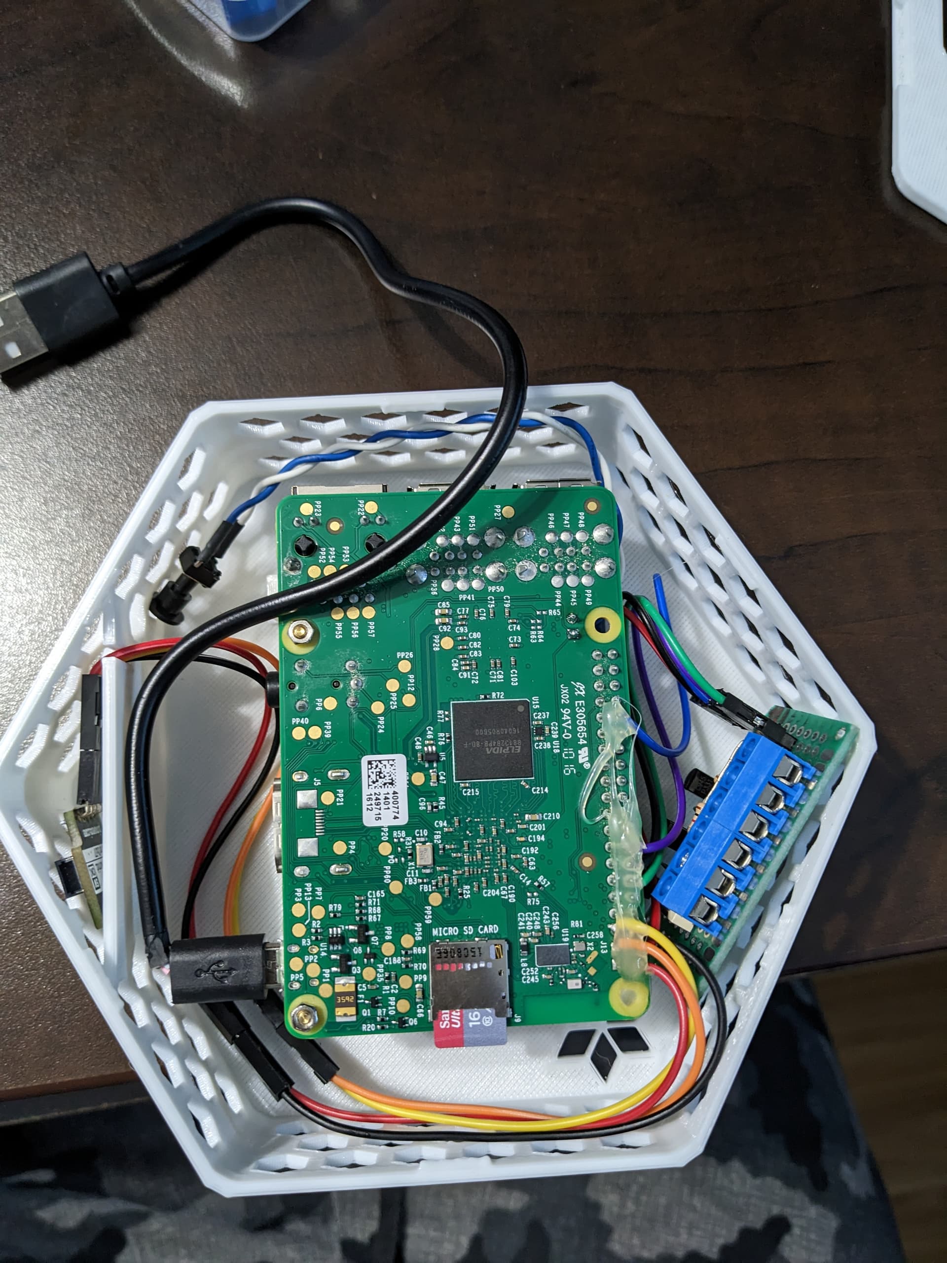
So i decided to keep the standard case mesurement and try my best to stuff everything inside.
It went pretty good as my friend gave me a hand with the custom circuit board required to run the relays.
Long story ahead
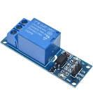
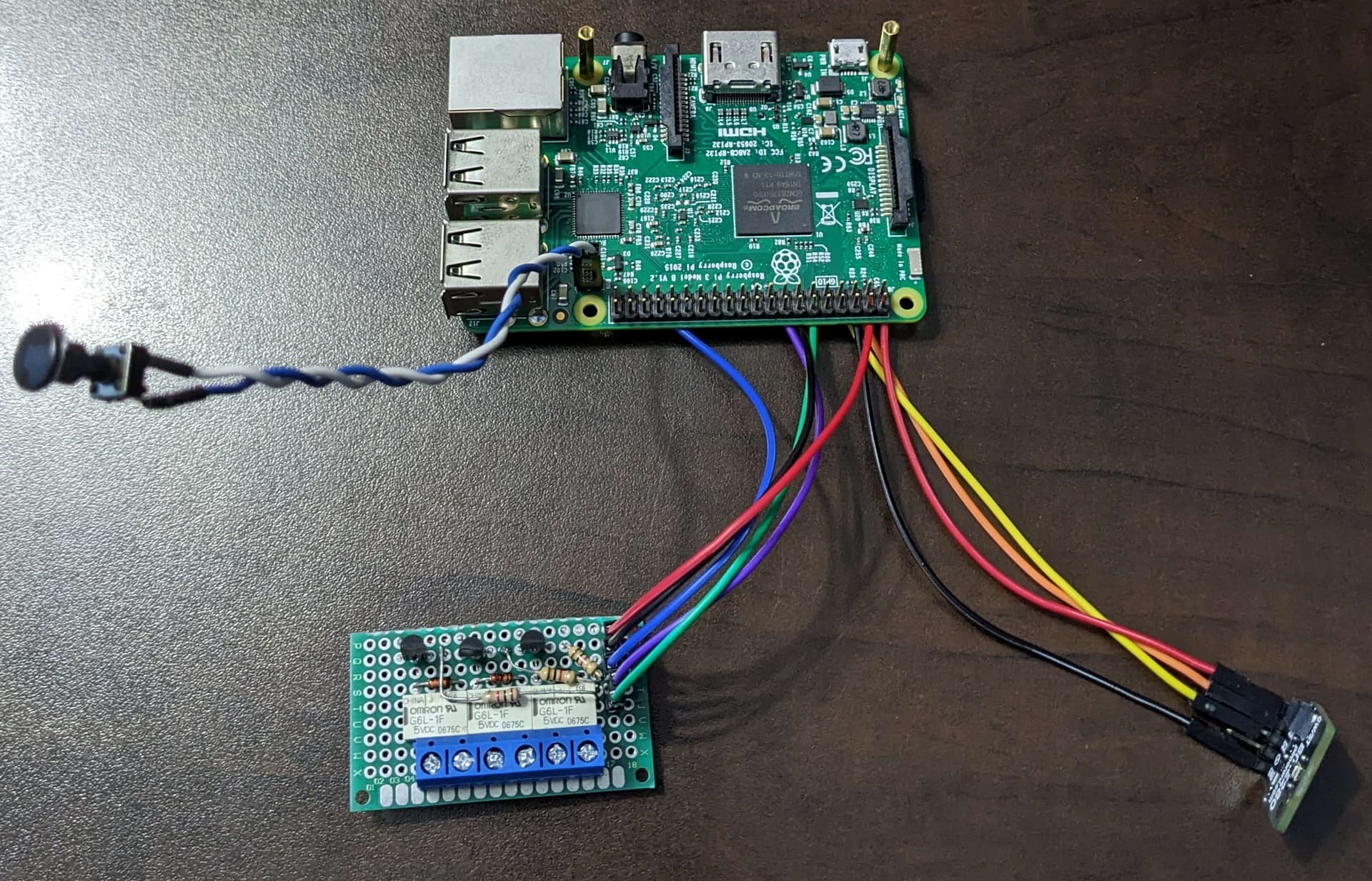
That part is important for anyone who’s willing to rework the way this projet behave, for exemple having to use DC Relay instead of AC SSR(Solid State relay). Both relay operation dont have the same effect on the RPI Board. Keep in mind that the total output for all GPIO is 50ma and each pins are 18ma for pullup. The SSR is a “contact less” relay so the input is isolated and require few ma to operate. The DC relay wich is mecanical have some caracteristic that can be chalenging. The input require more power and the fact that it use a coil, that can create a “bounce back” on the GPIO pin wich can “toast” the board(or the GPIO).
So with that in my we needed to boost the output of the GPIO and create electronic isolation between the relay and GPIO.
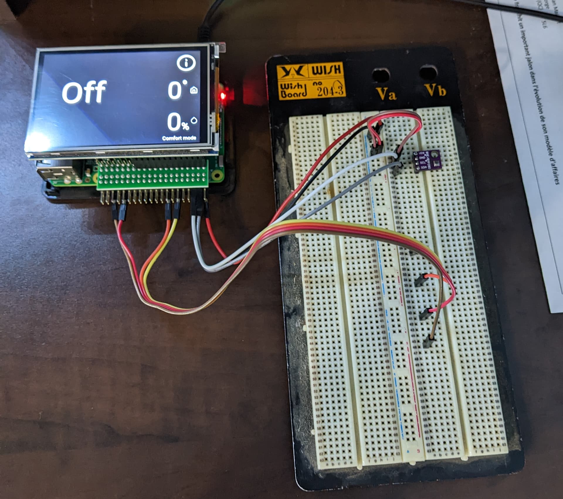
This was done using somes transistors/resistors/diodes and a little project board. Its not as pretty as a factory made board but it works! (see picture below).

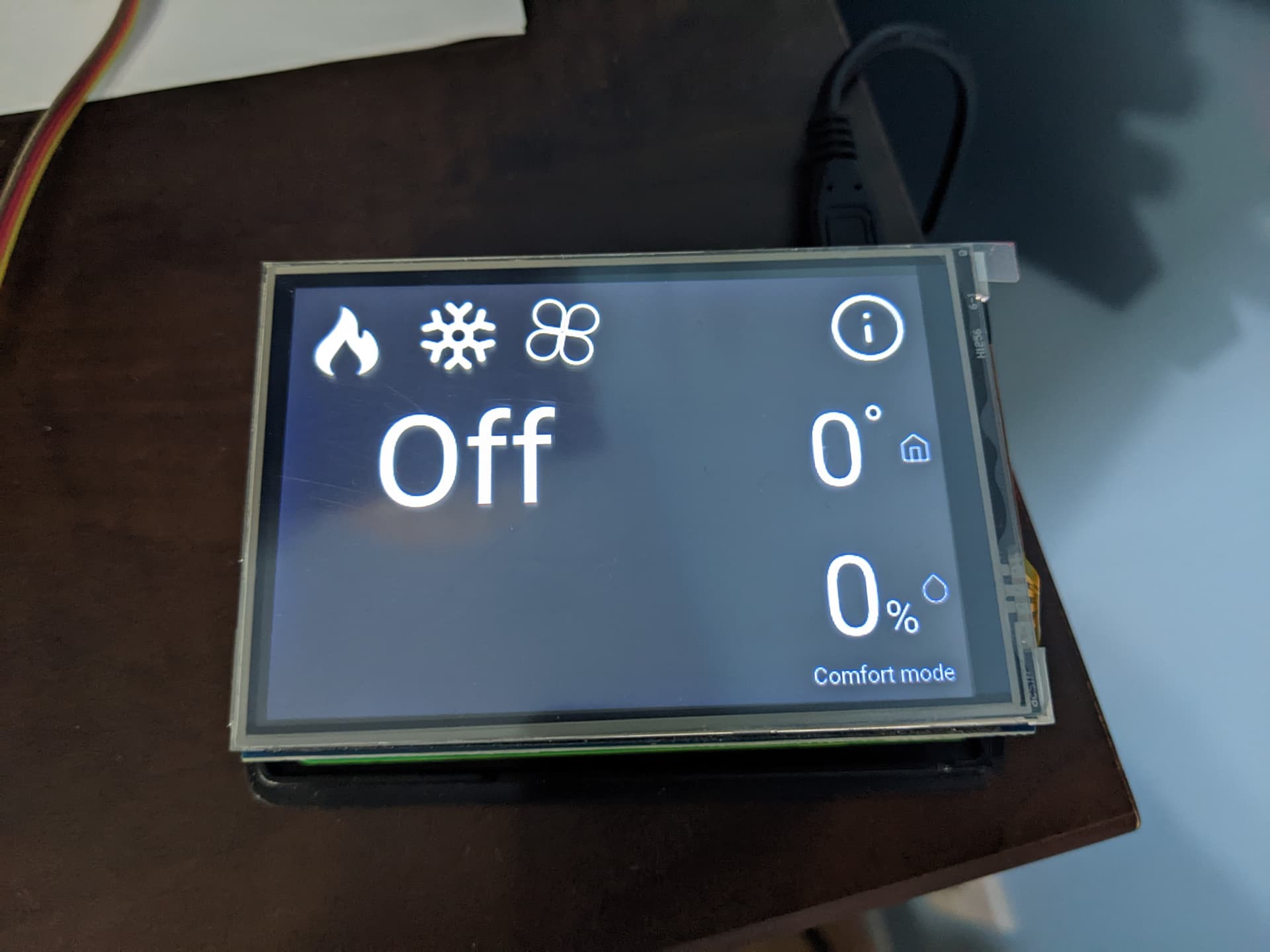
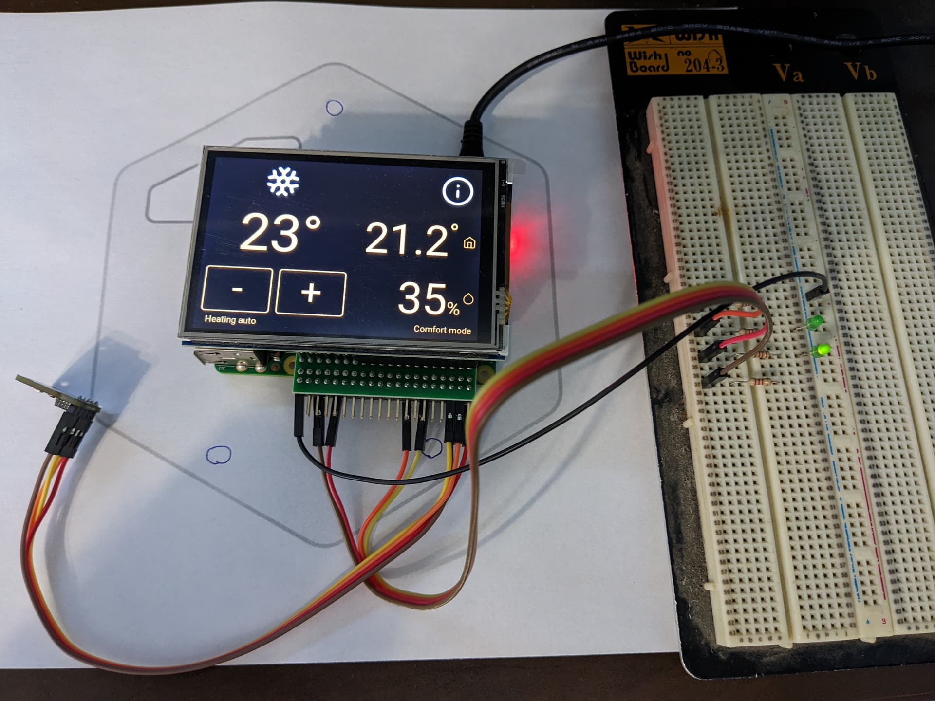
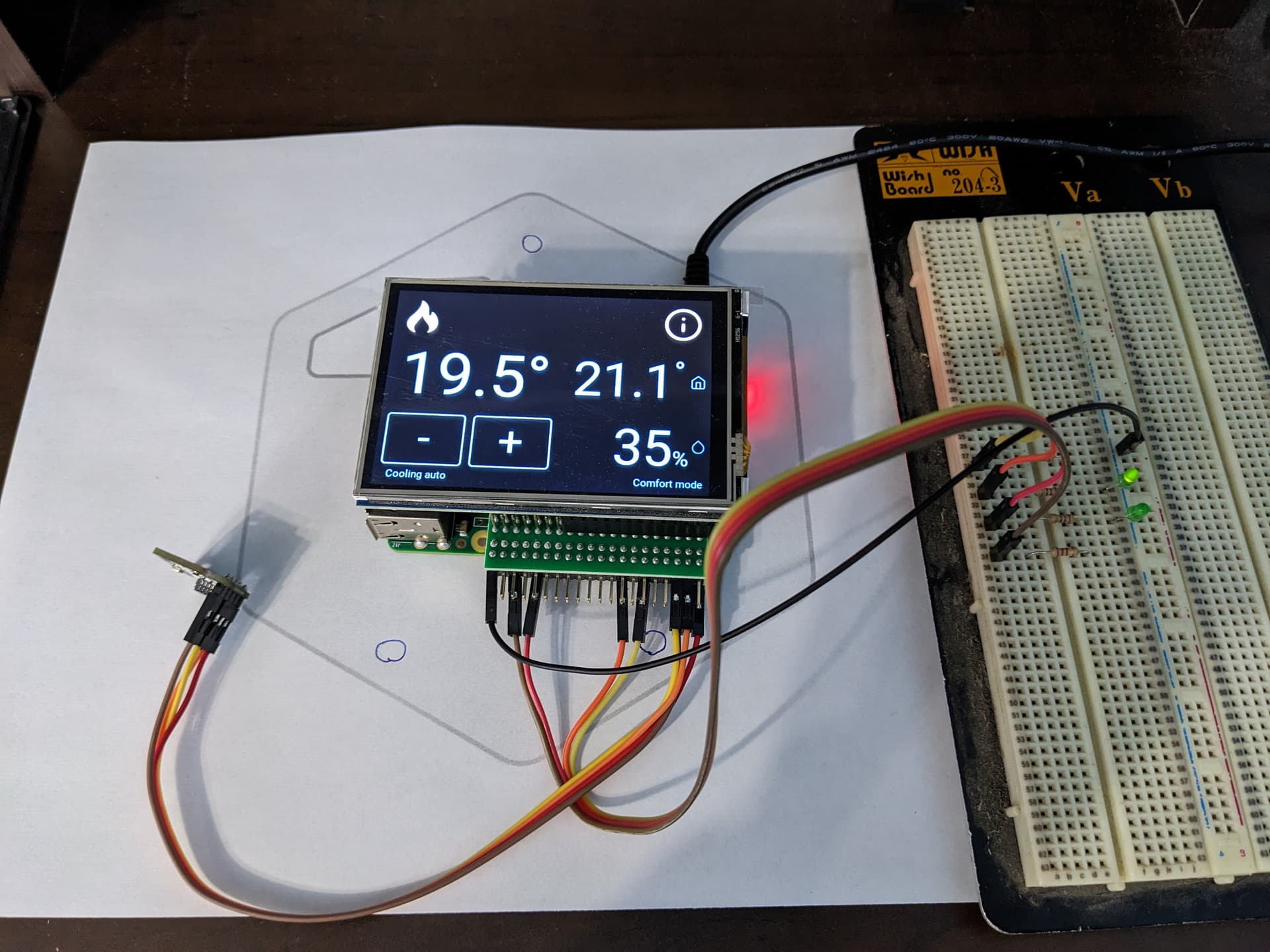
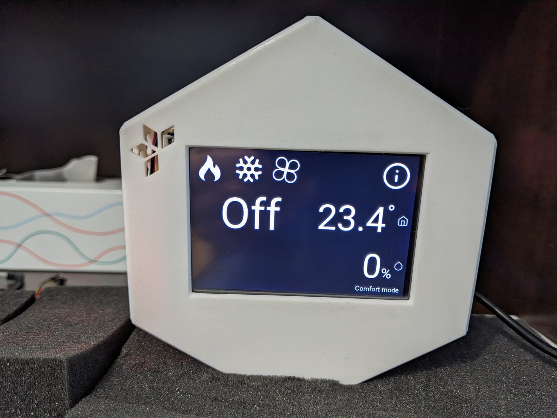
So after all of this i have a fully working Hestiapi thermostat running on Rasbperry Pi3b+.
But i have two issues to solve:

1-The LCD screen i’m using is upside down. I have to find how to manage this from the software or OS side. It use same XPT2046 controler so the SDK should be also the same as the original one. *If someone have a clue let me know plz :slight_smile:

2-I cannot screw the PI on the backplate so everything is holding to the screen and the three little tabs that hold it in place. I already craked one while inserting the screen. I might have to reenforce them with glue or find a way to fix the Freecad file and alter the design.

Sorry for writing my whole story, i make this so it can stimulate other to do some DIY.
Here are my pictures of the project so far!


Edit: I managed to make it work! But then the touch i started acting backward:
I fliped the display by adding dtoverlay=waveshare32b:rotate=270 in /boot/config.txt but the touch remaned backward. I wasn’t able to lunch “xinput_calibrator” due to an error and i ended up crashing my PI Image. So i re-image the SD card then this time i followed the procedure used when you do a manual installation but only the LCD part:
https://github.com/HestiaPi/hestia-touch-openhab/wiki/Manual-Installation-ONE#lcd-start

Blockquote LCD START

wget http://www.hestiapi.com/download/LCD-show-170703.tar.gz \
&& tar xvf LCD-show-170703.tar.gz \
&& cd LCD-show/ \
&& sudo ./LCD35-show;

Pi reboots with LCD working and stops at console prompt.

sudo rm -rf /home/pi/LCD-show LCD-show-170703.tar.gz;

sudo dpkg -i ./LCD-show/xinput-calibrator_0.7.5-1_armhf.deb \
&& sudo rm -rf LCD-show* \
&& sudo mkdir /etc/X11/xorg.conf.d \
&& sudo touch /etc/X11/xorg.conf.d/99-calibration.conf \
&& echo 'Section "InputClass"
  Identifier        "calibration"
  MatchProduct        "ADS7846 Touchscreen"
  Option        "Calibration"          "3900 218 246 3832"
EndSection' | sudo tee /etc/X11/xorg.conf.d/99-calibration.conf;

sudo DISPLAY=:0.0 xinput_calibrator

I dont understand why it i have to re-run the calibrator after each reboot.
I guess i need to set something to make this permanent?

Regards
Christian

Well i worked so fast i did not pay attention to the SSH console and there was a message telling how to make this permanet.(eyes rolling)

→ Making the calibration permanent ←
copy the snippet below into ‘/etc/X11/xorg.conf.d/99-calibration.conf’
Section “InputClass”
Identifier “calibration”
MatchProduct “ADS7846 Touchscreen”
Option “Calibration” “199 3881 3950 253”
EndSection

I think i can say that everything is fully working :sweat: :rofl:

1 Like

Keep an eye on the temperature of the Pi and the reading of the temp sensor as a whole Pi (compare to a Zero) consumed much more power and produces much more dissipated heat and the minimum passive air flow may not be enough, especially on hot Summer days…

Yup that it something i’m going to check. Also this give an error reading temp by about .5 degre due to internal heat.

It runs st 45 degre but i’m not sure what is the critical temp for the CPU.

This topic was automatically closed 91 days after the last reply. New replies are no longer allowed.