Hestia32 - An update

Happy New Year! We’ve made significant progress on the Hestia32 - New model? project, our next-generation ESP32-based thermostat controller. Here’s where we stand:

Hardware Components:

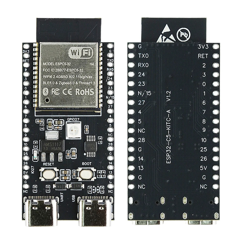
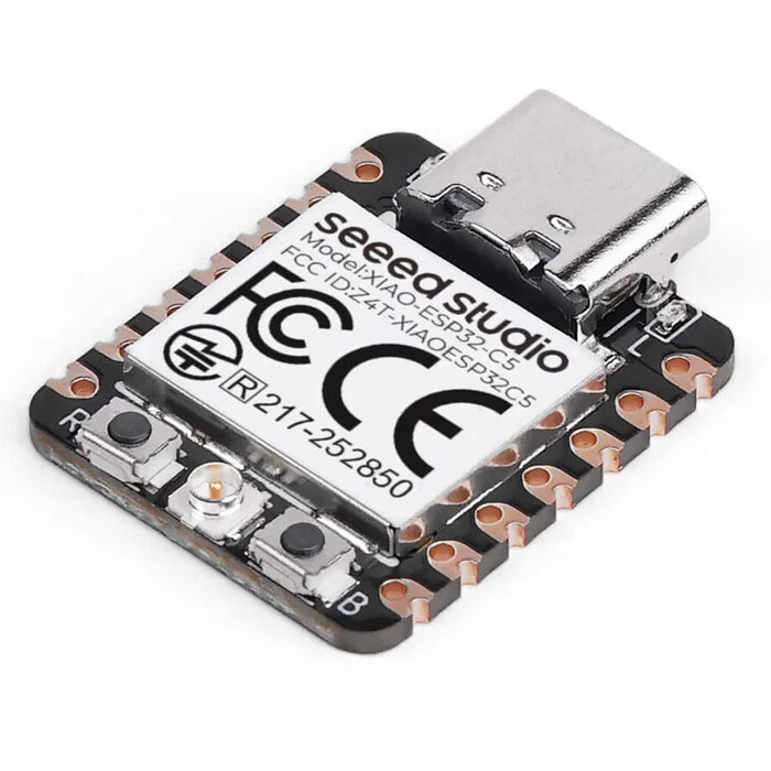
  • ESP32-C5 microcontroller

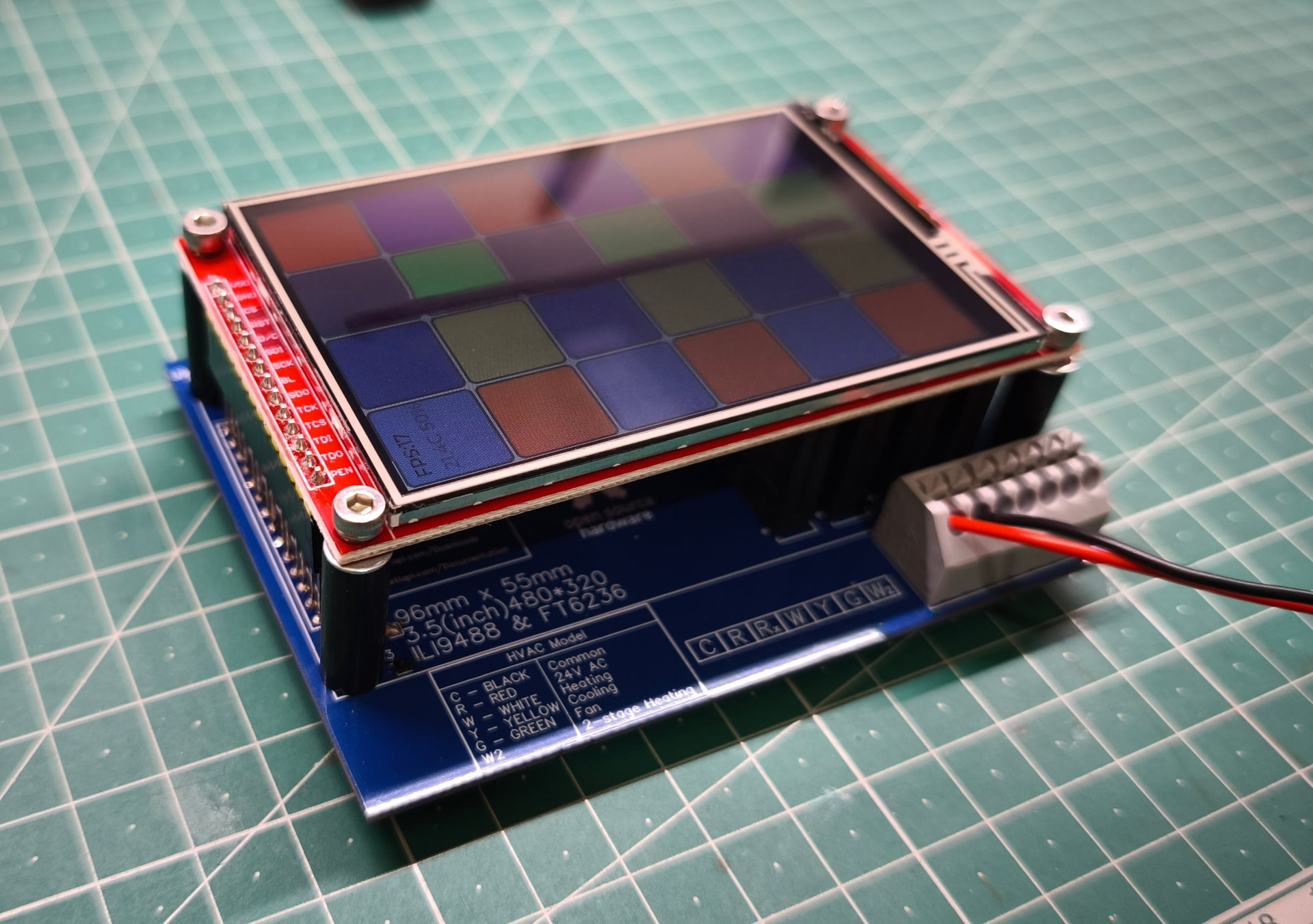
  • IPS 3.5" touchscreen display (SPI with ILI9488)

Key Features:

  • MQTT over WiFi (both 2.4 and 5GHz)

  • Zigbee

  • Matter over WiFi

  • Matter over Thread

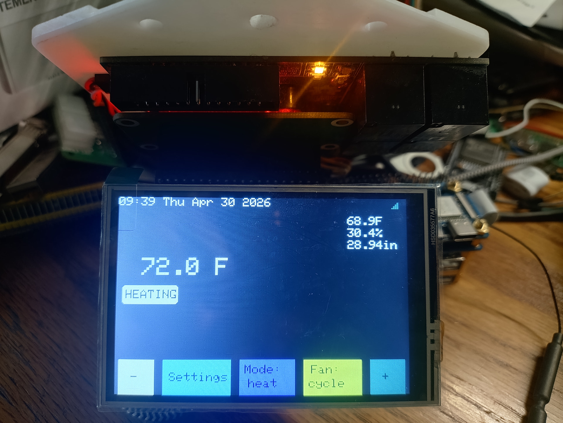
  • LVGL-based touch UI for smooth, responsive interface

  • Firmware updates with rollback protection

We’re currently focusing on display optimization and sensor integration. The platform maintains the simplicity HestiaPi users expect while offering flexibility for different use cases.

As this will be a client-based approach, an existing (agnostic) smart home server will be expected, while keeping full offline functionality as a standalone thermostat alone.

Looking forward to hearing your thoughts on feature priorities and what you’d like to see supported!

The main idea is to:

  1. Get everybody’s view on a feature set
  2. Make an MVP
  3. Build a few prototypes
  4. Kick off another crowdfunding campaign
  5. Support the full feature set with firmware updates (locally over BLE or the screen itself from GitHub releases)

The key features outlined in the original post seem like more than enough as far as I’m concerned. I don’t really want or need most of that, but as long as I can disable them (or at a minimum the Zigbee radio), it’s cool.

Rollback protection

I’d like to request that there be some way to roll back to old versions of the firmware. I’ve been bitten too many times where an update causes some feature to break, or it gets removed, or something like that and I can’t go back to the version I liked because of anti-downgrade "protection”. I understand the motivation for such restrictions, but in my experience it’s caused far more problems than it’s prevented.

I think an acceptable compromise would be to allow wiping+flashing an old version onto the device. This allows people to run the firmware version they want, while giving people are concerned that an attacker will downgrade the firmware on their thermostat and steal/abuse their MQTT credentials.

Initial setup

I want the initial setup to be as easy as it is with the HestiaPi ONE.

I mention this because it’s been on my mind lately in that I’m not sure how I’m going to make the UI for the ONE connect to another server. Maybe a customized version of the turnkey project (which seems like it’s abandoned at this point anyway)? I dunno, but I wanted to mention it because ease of use is a strong point of this project and I want to make sure that remains to be the case with future versions that add features.

Random thought

It might be cool to have an option to couple this with a Raspberry Pi 4 that can run the home automation software of the user’s choice (all in one case). That could help the people who want to just plug and play and get all the smart thermostat features.

Maybe this idea is for the future, after the MVP?

I like the idea of having an “All in One” option though, off the cuff I would also recommend the option of selling a companion central server with the client(s). That could be helpful when having many thermostats.

Rollback

There will be no rollback protection. In fact the ESP holds 2 partitions for firmware. One is the active one that currently runs. Any new firmware will be stored in the second one and if it succeeds in booting into, it will be marked as the new active and will be used in following reboots. This allows peace of mind for possible bricking as it will “automatically“ go back to last good-known-working version. Remember this will be fully open source and open hardware, encouraging users to fork and tweak the code to their liking so we made sure it will be “brick-safe“.

Also a factory settings feature (keep a special button pressed for some seconds on boot) will erase all settings and boot into a clean firmware if a user tweaked it too much :slight_smile:

Features

As there will probably be no immediate app for now, all configuration and features will be available on the screen to enable/disable at will. If firmware grows too large to fit all WiFi, Zigbee and Matter in the same file, we may distribute separate firmware to flash whichever is needed.

We have already started developing the main thermostat logic in a private repo till there is a prototype or BoM for others to play with. Here are some of the features that are 100% developed and tested:

  1. Configuration validation - Domain limits, setpoint sanity checks

  2. Hysteresis protection - Prevents rapid state changes (300s delay)

  3. Comfort deadband - Temperature activation thresholds (±0.5°C)

  4. ECO deadband - Wider temperature band for energy savings (±1.0°C)

  5. Stage 2 heating - Gradual power increase with delay + deviation logic

  6. Stage 2 cooling - Gradual power increase with delay + deviation logic

  7. Mutual exclusion - Heating and cooling never run simultaneously

  8. Sensor failure safety - Automatic shutdown on sensor faults

  9. Temperature units - Celsius and Fahrenheit conversion

  10. Fan control - Pre-run (30s), post-run (60s), and manual override

  11. Humidity control - Humidification and dehumidification with deadband

  12. Hot water demand - On-demand hot water heating

  13. Fan timing - Comprehensive pre-run and post-run validation

  14. Hysteresis + HVAC - State change delays with fan coordination

  15. Comfort deadband + HVAC - Temperature thresholds with fan safety

  16. ECO deadband + HVAC - Energy-saving mode with fan coordination

  17. Stage 2 heating + HVAC - Multi-stage heating with fan timing

  18. Stage 2 cooling + HVAC - Multi-stage cooling with fan timing

  19. Mutual exclusion + HVAC - No simultaneous operation through all fan phases

  20. Sensor failure + HVAC - Immediate shutdown including fan (safety critical)

  21. Open window detection - Detects rapid temperature drops, suspends heating to save energy

  22. Open window false positive prevention - Validates gradual changes don’t trigger detection

As we have wasted too much time testing on the touchscreen the various scenarios, the above logic is split from the main firmware (that is hardware-related) and can be compiled and run on any PC with gcc compiler. The reason behind that is that we developed tests for each feature and we can run all of them in a seconds simulating input parameters (settings stored, setpoints set, sensor values, elapsed time) and confirmed expected with actual output. If something fails, code is fixed on the same PC. The fixed code is then imported into the firmware. This saves so much time!!!

Initial setup

Almost identical UI from “turnkey” is already developed. If WiFi credentials are correct it reboots into main UI. If not, it reboots again into provisioning Access Point to repeat. As this is an ESP, either of these scenarios are instant (boots in 2 seconds)

Instant support

What you mention is called discovery and is already in our specifications so that OpenHAB and HomeAssistant pickup what this new device (Hestia32) supports and prepare the UI with ALL needed elements in ONE step. This is important and will be in the MVP!
Not sure if it will make sense (commercially) to bundle it with a Pi 4 with an SD pre-flashed to one of the home automation… I mean it could simply be an SD image to download. Where is the added value to pre-flash an SD card and resell a Pi with a case and a power supply? Anyone can do that on their own to avoid paying us do it for them. Unless you are talking about putting a full Pi 4 inside the case of the Hestia32 which is going to be a huge case on your wall that generates too much heat to get accurate readings and requires a much bigger power supply. I think we’ve reached a point where “everyone“ has a smart home server. Either in their house local or the cloud (Google, Apple, Alexa).

It’s been a month since the last update and a lot have happened since then.

Software

Added remaining features:

  • Boost for heating, cooling and hot water
  • Added SHT45 temperature and humidity support (we will not use BME280)
  • Non volatile memory used for storing user settings and previous states in case of power failure/reboot
  • CI/CD. Github will test code, run all test cases and generate all needed binary files automatically to create a new public release (once a tag is pushed to appropriate)
  • Automatic OTA (Over The Air) updates (defaulting to off for privacy purposes). People will automatically get latest (stable or development) firmware once a new release is published on GitHub. Keep in mind there is already in place the mechanism to detect if a new OTA was installed (in second partition) and run correctly, otherwise it automatically reverts back to the last good known partition.
  • MQTT and LCD UI: These are the only ones missing right now before the Github repo is converted to public for people to start having a go at

Business

We have been contacted by a major Shenzhen manufacturer to work together in order to get help with the expected volume. They will handle sourcing parts, PCB, PCB assembly, packaging, warehouse, logistics, duties, shipping and first level shipping support. This will speed things up and let us work only on the fun parts that we enjoy! A few modifications were suggested to optimise cost and speed and we are verifying them as we speak to move forward.
Crowdfunding is also running. We may do both the campaign and the collaboration with the manufacturer to get maximum traction but we haven’t finalised the terms yet.

Once things are final, the repo will go public with master and develop branches with an alpha release and the business decisions announced.

We said we would open the repo once the next milestone was ready, and now that is done.

Hestia32 is now public:
https://github.com/MakeOpenStuff/hestia32

And the first public release is live:
https://github.com/MakeOpenStuff/hestia32/releases/tag/v0.9.0

What is in place right now:

  • Public main and develop branches

  • Automated CI/CD pipeline (builds, tests, release artifacts on tag)

  • OTA workflow with rollback safety already in place

  • Boost for heating, cooling and hot water

  • SHT45 temperature/humidity support

  • Non-volatile settings/state handling

  • Ready PCB files (Gerber, BOM and schematics)

Protocol status:

  • MQTT: implemented and active path

  • Zigbee: framework/stub in place

  • Matter: framework/stub in place

Big thanks to everyone who followed along and gave feedback while this was still private.
Now that everything is open, please have a look around, open issues, suggest priorities, and tell us what you want next.

Next stop? UI design!

Right now the screen only shows a dummy animation to test the display library, touch, refresh rate and basic LVGL layout. The final UI will be based on LVGL and comprehensive guides supplied will allow people to customise what information and controls will be available at the screen. Should we reuse the old UI or kick it up a notch with something fresh?

Then a 3D printable case :wink: !

Hardware options

Sticking to our word, the components chosen are easily available by more than one supplier so the ESP32-C5 DevKit is chosen. To also support mass production by a factory, compatibility with an additional open source/hardware board (Seeed’s XIAO ESP32-C5) will be maintained. So all models (HVAC and EU) will be available in 2 PCB choices. One for the DevKit (for DIYers) and one for the XIAO (sold by our shop) in order to have an open source product regardless of the path you chose. XIAO is implemented first but very soon the DevKit will be added in the repo (in /pcb folder).

@jrtaylor71 Thank you for your swift review!

Moving the discussion here to keep it tidy.

1. The power supply for both boards needs RF suppression.
2. I would not use solid state relays. There has been talk about new systems being DC.
3. The ESP32-S3 is a better fit for the core system with a C5/H2 to provide 802.15.4.
4. The C5/H2 could be setup on a socket so that it could be built with or without them.
5. Provide multiple sensor support. xDTxx sensors and the BMExxx.
6. Relay drive options would be a ULN2803 or MCP23017.

My comments (following the numbering):

  1. Could you suggest components/part numbers for each model?
  2. We like the silent operation to be honest and the use of 4 components instead of 4x4=16 for easier hand soldering. How big of the pie do you believe we are missing out by choosing solid state? For those who may not know, the solid state relays (SSR) can only control AC signals and not DC. So far HestiaPi was using these same SSR so we simply reused the design.
  3. So you suggest an S3 for simple WiFi model and an additional C5 for models with Zigbee/Thread? This adds more complexity but I cannot see the benefit as C5 seems like it handles ok the load even just by itself
  4. -
  5. The use of SHT45 was suggested by the factory as a more precise but economical option compared to BME280 used before. Regarding the hydronic support, don’t they still sense the air indirectly and not attached to the water pipes themselves?
  6. -

When I was doing research to add matter and zigbee to my project I came across this display board.

A simplified version of this would work well for what you want.

As for the relays I think it is going to be a problem that is going to come up later but I have seen those types of SSP’s get burned out very easily. The best way to handle this is either make 2 boards or setup the board to accept either relay. I would do the dual relay option.

Comparison table

Sensor Measures Interface ESP32 voltage fit Accuracy / usefulness Best use My opinion
DHT11 Temp, humidity Single-wire digital 3.3–5 V modules exist Rough. Common specs are about ±2 °C and ±5% RH, limited to roughly 0–50 °C and 20–90% RH. Cheap learning projects Do not use for anything you care about
DHT22 / AM2302 Temp, humidity Single-wire digital Usually 3.3–5 V Better than DHT11, but still slower and less robust than modern I²C sensors Low-cost outdoor-ish temp/RH Acceptable, but dated
BME280 Temp, humidity, barometric pressure I²C or SPI Native 3.3 V sensor; many breakout boards tolerate 5 V Common breakout specs: humidity around ±3% RH, pressure around ±1 hPa, temp around ±1 °C. Weather station, altitude/barometer, room climate Very good general-purpose choice
BME680 Temp, humidity, pressure, gas resistance/VOC trend I²C; some boards SPI Native 3.3 V sensor; many breakouts tolerate 5 V Bosch describes it as a 4-in-1 gas, humidity, pressure, temperature sensor for indoor air-quality applications. Indoor air-quality trend, cooking/chemical odor detection Good, but gas reading is not “real CO₂”
BME688 Same as BME680, newer gas AI-capable variant I²C/SPI depending board 3.3 V Similar role to BME680, with newer gas-analysis features Advanced IAQ experiments Better than BME680 if price is close
SHT40 Temp, humidity I²C 1.08–3.6 V class Good modern humidity sensor Basic high-quality temp/RH Good
SHT41 Temp, humidity I²C 1.08–3.6 V class Better full-range RH accuracy than SHT40 Better temp/RH Very good
SHT45 Temp, humidity I²C 1.08–3.6 V, excellent for ESP32 3.3 V Sensirion lists ±1.0% RH and ±0.1 °C typical accuracy; supply range is 1.08–3.6 V. Accurate room temp/RH, dewpoint, HVAC control Best temp/RH sensor here
SGP40 VOC index only I²C 3.3 V Designed for VOC-based indoor air-quality signal, humidity-compensated, intended to feed Sensirion’s gas index algorithm. VOC trend sensor Good add-on, not a complete air sensor
SCD40 / SCD41 Real CO₂, temp, humidity I²C 3.3 V modules common Real NDIR CO₂ sensor, much more meaningful than “eCO₂” VOC estimates Ventilation monitoring Best for actual CO₂
PMS5003 PM1.0, PM2.5, PM10 particulates UART Usually 5 V power, 3.3 V logic commonly usable depending board Laser scattering particulate sensor; outputs suspended-particle concentration digitally. Smoke, dust, wildfire air quality Good budget PM sensor
SPS30 PM1.0, PM2.5, PM4, PM10 UART/I²C depending module ESP32-compatible modules available Higher-end particulate sensor than PMS5003 Better long-term PM monitoring Better, more expensive

This is a great off-the-shelf solution for many projects indeed. My main objection though for an open project is that it is only made by one company and if “tomorrow” becomes discontinued the project is in trouble.

Regarding the SSR, we’ve used that exact component in the crowdfunding campaign and the following production batches with returns below the expected numbers over the following two years. This is why we went blindly to the same “tried and tested” design to minimise the risk.

I agree with you I just threw that out there as an example.

Key Drawbacks of Solid State Relays:

Heat Generation: SSRs produce heat due to internal voltage drop (typical), often requiring heatsinks or fans to prevent failure.

Leakage Current: Even in the “OFF” state, a small amount of current leaks through, which can cause issues in sensitive, low-power applications.

Sensitivity to Surges/Spikes: Semiconductors are vulnerable to voltage spikes and surges, requiring protective circuitry (snubbers, varistors) to prevent damage.

Higher Cost: Generally, SSRs are more expensive than traditional mechanical relays.

Voltage Drop: A fixed voltage drop occurs at the output, causing reduced efficiency compared to the near-zero resistance of mechanical contacts.

Failure Mode: Unlike mechanical relays that may fail open, SSRs often fail in a short-circuit (closed) condition, which can be dangerous.

Limited Overload Capacity: SSRs do not handle high inrush currents as well as mechanical relays, making them less suited for certain motor loads.

Parallel Limitations: Outputs cannot be easily connected in parallel to increase current capacity.

Common Failure Causes:

Thermal Stress: Insufficient cooling leading to rapid degradation.

Overvoltage/Overcurrent: Transients surpassing semiconductor limits.

Improper Wiring/Environmental Contamination.

Again just trowing this out there. This type of equipment is becoming more common. I have personally have used these and they work very well. The SSP’s will not work with this type of equipment and I have heard talk about more of this kind of stuff in the HVAC world. I have forced air hydronic heat that runs off an open loop boiler. The air handler like this is one example of what they are talking about switching.

Would it be much effort to use the SHT45 with the ONE model instead of the BME280? If it’s cheaper and more accurate, it seems like that’d be a nice upgrade for existing users, if it’s something that can be dropped in.

Just a comment about HVAC ststems and 24VAC control systems based on my own experience: WaterFurnace brand heat pumps use propriatary control system that operates over RS485, however, they can alternatively support the standard 24VAC controls (as long as you only have one zone). A traditional (clicky) relay system would not work with the RS485 system, nor would it work any better than SSRs with the standard control system.

A comment on the claim (which looks sloppypasta) that SSRs are likely to fail due to power surges, spikes, overload capacity, thermal stress, etc. I’m not aware of a single reported failure of the SSR that this project has ever used. I’m not sure what the source is that is claiming they’re failure prone, but our experience demonstartes that’s not the case, at least with this specific model being used in the way that we are using them.

Finally, I’d just like to reiterate how much I appreciate this new model being designed with components available from multiple sources, and remaining DIY friendly. These are values I share and seeing them put into practice like this makes me proud to continue supporting/promoting this project!

Easy to add SHT45.

For the SSP’s it’s a use case but I have had them get cooked and get very hot..

I have a fully functioning HestiaPi/StackFi working. You could run this on a DevKit with a few jumpers too. I have one problem with StackyFi and that the WiFi antenna is in the way. Going to contact them about using an ESP32-S3 with an external antenna.

Relays
Pin RPI GPIO ESP GPIO
Relay1 32 GPIO12 GPIO17
Relay2 16 GPIO23 GPIO14
Relay3 12 GPIO18 GPIO47
Relay4 36 GPIO16 GPIO7

LCD
PIN NO. SYMBOL DESCRIPTION ESP GPIO
1, 17 3.3V Power positive (3.3V power input)
2, 4 5V Power positive (5V power input)
3, 5, 7, 8, 10, 12, 13, 15, 16 NC NC
6, 9, 14, 20, 25 GND Ground
11 TP_IRQ Touch Panel interrupt, low level while the Touch Panel detects touching GPIO38
18 LCD_RS Instruction/Data Register selection GPIO12
19 LCD_SI / TP_SI SPI data input of LCD/Touch Panel GPIO10
21 TP_SO SPI data output of Touch Panel GPIO11
22 RST Reset GPIO46
23 LCD_SCK / TP_SCK SPI clock of LCD/Touch Panel GPIO3
24 LCD_CS LCD chip selection, low active GPIO20
26 TP_CS Touch Panel chip selection, low active GPIO19

https://www.taylordatacom.com/wp-content/uploads/user-private-files/build_v1.4.016_20260430-191907.zip

I cannot test it right now but could you run this for me? I haven’t run it myself. Keep in mind, pressure is not included now in the output so its absence must be taken care of.

#!/usr/bin/env python3

import smbus2
import time

I2C_BUS = 1
SHT45_ADDR = 0x44  # change to 0x45 if needed

bus = smbus2.SMBus(I2C_BUS)

# High precision measurement command (no clock stretching)
CMD_MEASURE = [0xFD]

def read_sht45():
    # Send measurement command
    bus.write_i2c_block_data(SHT45_ADDR, CMD_MEASURE[0], [])

    # Wait for measurement (~10 ms)
    time.sleep(0.01)

    # Read 6 bytes: T(2) + CRC + RH(2) + CRC
    data = bus.read_i2c_block_data(SHT45_ADDR, 0x00, 6)

    temp_raw = data[0] << 8 | data[1]
    hum_raw  = data[3] << 8 | data[4]

    # Convert (from datasheet)
    temperature = -45 + 175 * (temp_raw / 65535.0)
    humidity    = 100 * (hum_raw / 65535.0)

    return temperature, humidity


if __name__ == "__main__":
    try:
        t, h = read_sht45()

        # Match typical HestiaPi output format (important!)
        print("Temperature: {:.2f} C".format(t))
        print("Humidity: {:.2f} %".format(h))

        # No pressure
        print("Pressure: N/A")

    except Exception as e:
        print("Error:", e)

There are boards like this one that share the same pinout as the BME280 (drop in replacement):