HestiaPi ONE - Detailed BOM

I am very interested in building or buying a unit. Your BOM seems good enough, but a little vague, is there any chance you could recommend part numbers at least? Getting the PCB is something I’ve never had to tackle before either. I’m confident I can assemble this, but I’d like some confidence that I’m buying the right parts.

Do you have any estimate on when the US kits might be back in stock? Even if not the assembled Units.

Thanks.

1 Like

I assume you are referring to the LCD mostly as everything else is pretty simple to order by their name. There a few posts here on the forum with tried and tested links for the LCD from US (Amazon I think) or Asian market. Let us know if you get stuck somewhere.
Regarding the PCB, we recommend jlcpcb.com

Thanks!

I think my primary concern is the power supply. The HLK-PM01 (which is listed as EU), and the link in the BOM for the US PSU, IPS-ATD24S53, are physically pinned differently. That is the UK version uses pins, and the US uses copper wire leads. The PCB is designed to accept the EU PSU, unless there;s a US specific PCB that i’m missing? Will the wiring of the PSU be straight forward? Looking at pictures of the board I’m a little Iffy there.

And yes, i havent even started looking for the display yet. I had assumed that was an off the shelf RPI touch display, is that not the case?

Thanks!

The PCB supports both the HLK and the ATD24S53. So don’t worry about it. There are also links on the forum for suppliers for this as our supplier only offers bulk. The LCD is not the official RPi LCD. Check the tried and tested links I mentioned.

Thank you for the info.

And sorry if i’ve hijacked this thread. :wink: I think I’m close to a list of components. I am following the BOM listed here: https://hestiapi.com/pcb-one/

It lists a 4-pin male header, which i believe is for connecting the external sensor. That sensor is for humidity and temperature no? It doesn’t list the sensor itself in the BOM.

Edit: I feel like This is the humidity/pressure/temp sensor: https://www.amazon.com/ALMOCN-Temperature-Humidity-Atmospheric-Barometric/dp/B08HJ6LFFQ/ref=sr_1_23?dchild=1&keywords=bme280&qid=1613001933&s=industrial&sr=1-23

Once I have this whole list together, ill be sure to share it, if anyone is coming here looking for this info.

The only other component I have left to find is the “long pin” connector for the display.

Thanks again!

I’ve moved us to a new thread to save you from the guilt :slight_smile:

Oops. This has been the sensor for too long and forgot to keep including its details:
BME280 powered @ 3.3-5.5V DC
Make sure you get it on a board/module (the BME is only the main tiny chip) and the board has 4 pins only, like below:
image
and NOT like below:
image
as the pinout on the mentioned 4-pin male header may differ and/or there may be a risk of killing the module.

A quick and dirty method, as they may not be available at 15mm lengths (we got them custom made), is to get longer pins and trim them with a cutter.

Here is an Amazon link for the power supply in the US:
SMAKN DC 5V/3A(MAX) AC/DC TO DC Buck Power Converter Voltage Step Dowm Power Supply Waterproof Input AC 7-36V/DC 8-50V https://www.amazon.com/dp/B00RE6QN4U/

You are correct, it is wire leads, and it solders onto the edge of the cutout section in the PCB.

A quick and dirty method, as they may not be available at 15mm lengths (we got them custom made), is to get longer pins and trim them with a cutter.

This is the sort of information that should be in the BOM, I dont recall reading anywhere what constituted “long” so the block I ordered may be too short now. I’ll have to test fit things once they arrive.

I ended up finding everything I needed, I think, only question remaining is whether the lcd connector block I ordered is going to work. Here’s my parts list:

First, The PCB, I ordered from OSHPark, I had to do a little work to get a board outline file, but once I worked that out, their site accepted your published gerber file. I went with them only because they were recommended by some local friends, and being in the US I expect the board will arrive sooner. They are more expensive than the place you’d recommended, and have a minimum order size, but if this all goes well I may be building more than one hestiapi anyway so that should be ok.

For the rest of the components, here’s my list I tried to get as much as I could from Mouser, again, a vendor im famaliar with and have used in the past:

Single row break apart pin header: https://www.mouser.com/ProductDetail/Molex/42375-1856/
4 of these OMRON relays: https://www.mouser.com/ProductDetail/653-G3MC-202P-DC5/
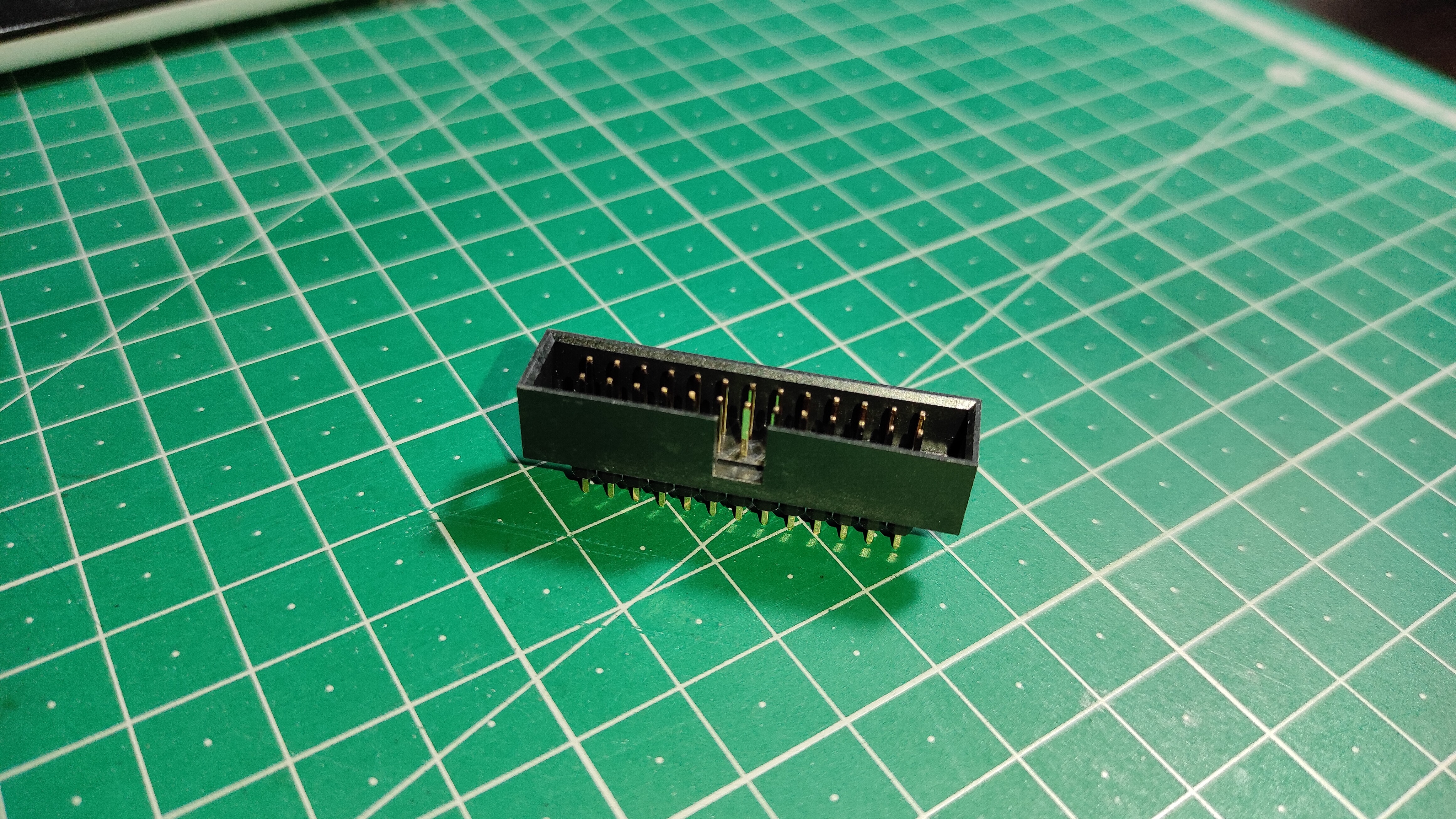
Connector for LCD *this may be too short: https://www.mouser.com/ProductDetail/TE-Connectivity-Alcoswitch/2-1761603-9/
Reset switch: https://www.mouser.com/ProductDetail/612-TL1105W/
6-pin Terminal block: https://www.mouser.com/ProductDetail/490-TB003-500-P06BE/

Then from amazon:
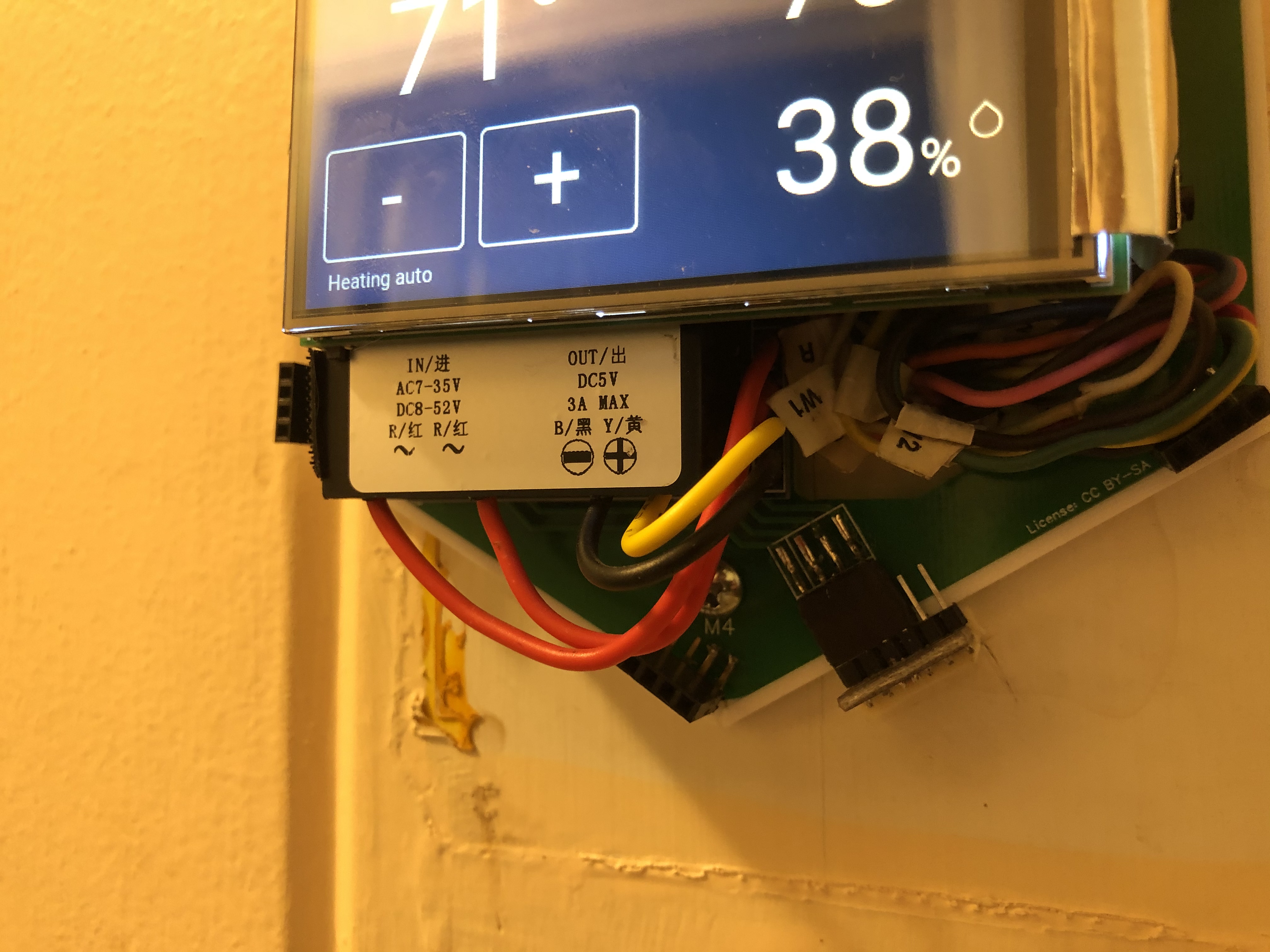
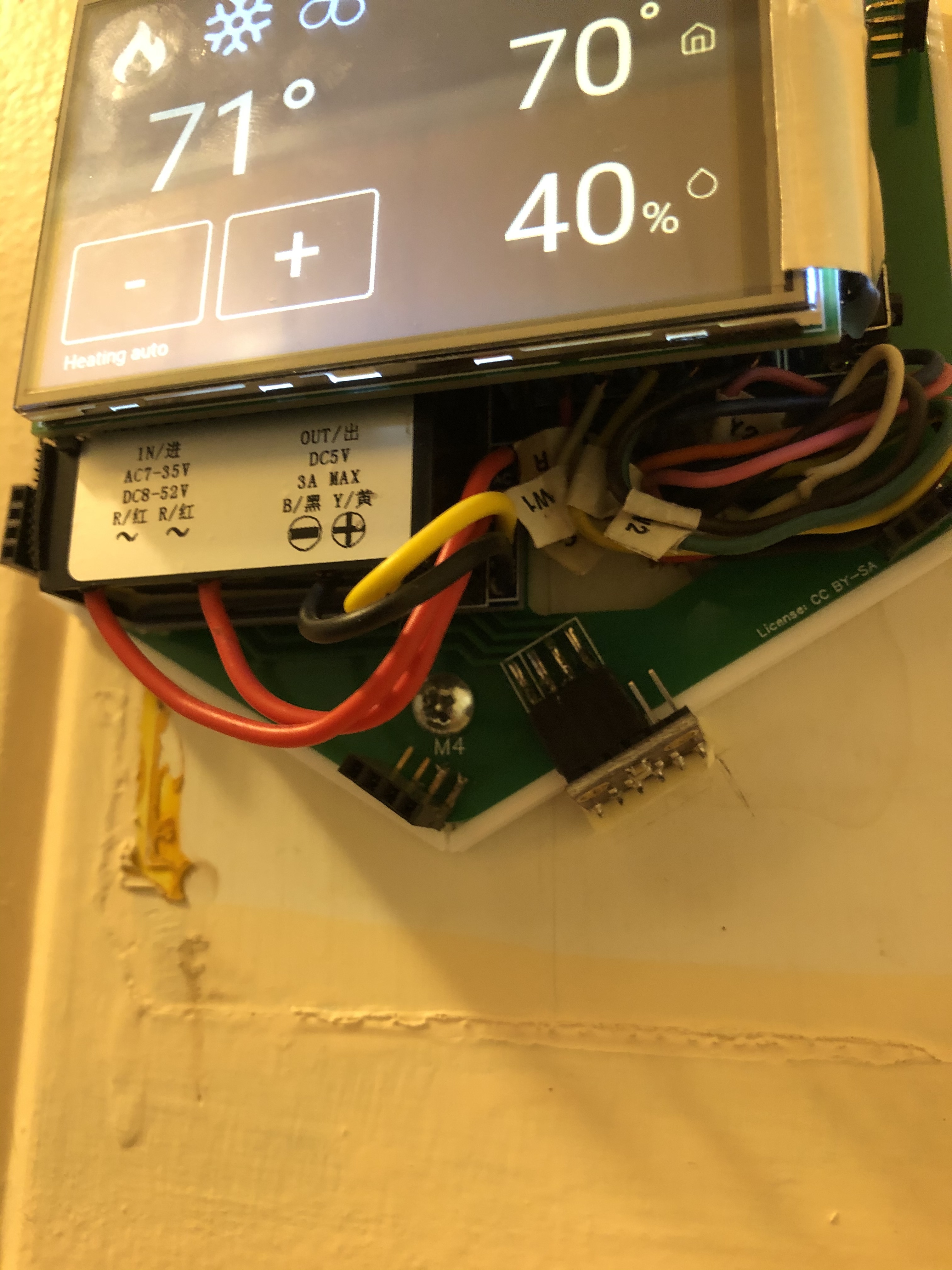
Power Supply: Amazon.com
Display: Amazon.com
Sensor: Amazon.com
Sensor Cable: https://www.amazon.com/dp/B0789F523N/

The only thing left is the RPI zero w, which i already have a few of laying around, so no big deal there.

I do have one question about the pin height, and the RPI 0.
I assume the length of the lcd connector pins is to account for the clearance of the pins on the GPIO block on the raspberry pi. right? The pins on the RPI arent used anymore though, are they? It looks like an older make of your board used the GPIO pins for the display, and then you moved to the dedicated connector.

This makes me curious, could the Pi be soldered in place with pins that ran through the pi and into the custom PCB instead of the way you do it now? Or is the GPIO block on the pi left in tact for some other reason I’m not aware of? Imagine taking the 40-pin header and placing it on the bottom of the board, instead of the top, then running the pins through your custom PCB and soldering them in place. Then the screen does’t need to clear the gpio block anymore.

Again, i may be missing something.

Thanks!

1 Like

You dont happen to have a picture of how its wired for reference do you?

Thanks!

This isn’t a great picture, as it has the LCD on top and the furnace wires connected, but it gives a general idea of placement and wiring:

hopefully we are talking about the current/newer HestiaPi TouchOne model. That is the one I have running.

The height of the PSU and the relays is what made us move from plugging it on the Pi directly and introduced the additional (long) header. “Moving” them outside the area the LCD covers may lower its overall profile but will take more space on your wall.

I would expect this would drastically reduce air flow for the Pi’s CPU. Obviously it would shift the main PCB up in the air. Securing wires at the screw terminal while standing mid-air sounds tricky (or impossible if live).
By the way your relay part is different and we haven’t tested these yet.

Now I’m trying to remember how I landed on those. I think while trying to find those specific relays, i’d come across a site that says they’ve been replaced with the ones I linked. I ordered them in the hopes that they’re compatible. Is there a reason to think they wont be?

This is definitely helpful… My concern now though is… that your PCB looks completely different than the one published here: PCB-ONE – HestiaPi (which is the board I had printed).

1 Like

input voltage is listed outside the Pi’s specs which was the case for previous part too but they worked fine so far. We are actually moving away from solid state relays in the next release to be honest despite their smaller size and silent operation so we will not be testing your part we are afraid.

2 Likes

So the board you printed is the same as mine. There are some standoffs from the hexagonal PCB below, that holds the PCB you printed. So it looks like we are talking the same model. If you have access to a 3D printer, your could print a base/case to hold your board.

The only thing you are missing would be the traces to move the BME280 sensor to the bottom right corner. This is on the hexagonal PCB.

1 Like

That makes me feel much better! My plan is to print the official case, but that hexoganal pcb was nowhere in the docs ive seen. The printed case has a little pocket at the bottom for the sensor, which then gets connected via a 4-wire lead.

Thanks!

1 Like

Just an update here!

I have my parts! Im going to start assembling things soon, there is one problem, and that is with the display connector. It is definitely too short. The problem is the clearance for the relays (as mentioned above). The relays stand off of the board such that they interfere with the display. I cannot connect my display using the header conenctor that i listed above. I am experimenting with a few things. One would be to use a ribbon cable, but that will, i think, make the case that Hestiapi has published un-usable for my build. The other option is to find a sufficiently spaced header for the PCB to connect the display to. This may be possible, but i’m having trouble finding one. It needs to be a bout 7mm of spacing between the display’s connector, and the printed pcb. An extension header might do the trick, but I havent found one yet that’s just right.

i ordered a ribbon cable, and ill give that a try. I also found some headers that use longer pins, with a shoulder on them. I don;t love that though as the pins are all exposed. I suppose with the case on it that shouldn;t really be a problem.

hestiapi, can you share the specifics of the connector block you had custom made?

1 Like

The male header pins need 15mm length and look like this:


The plastic surrounding is not that important.
A quick hack would be to remove the Pi’s original pins and find a strong enough wire that doesn’t bend easily and solder them on the desired height. Be careful sorting some pins while powered on may damage the Pi.

1 Like

@Gangrif Hope you are doing well.

I am trying to reproduce your setup. Did you set up everything correctly? Do you have any advice on choosing the display connector?

Thank you!

1 Like

I have yet to find a proper connector for the display. Also am not certain yet if the relays work, becuase I have to do some work to my heating system to make it work with the hestia.

I have a 26 pin spacer coming in the mail, which i THINK will solve my display mounting problem. Then I just need to work out converting my heating system from 2 wire to 3. after that I can actually test out the hestia. I do have it functional with a ribbon cable attaching the display, but I cant mount it on the wall like that. So before I hack up my heating system I want to solve that.

2 Likes