HestiaPi ONE - Detailed BOM

Folks, after all this time the hold up is still this damn display connector. I have tried 3 solutions now and cannot get the right spacing from the baord to the display in order to fit everything into the pre-made case. At this point I only see a few options.

  1. design a different case, which is no small task for me.

  2. scrap the whole damn project over a stupid connector.

  3. wait for Hestiapi to pick up production again, and order a connector from them.

All I really need here is a pin/header block thats about twice as long as standard. Then i could trim it down to the length i need. NO ONE seems to carry one of these, does anyone know where I might get one?

2 Likes

Option 3 will not be an option as the new production will support complete units only and not parts (production line will be based in Shenzhen).

1 Like

Thats just Wonderful.

Iā€™m also interested in building a couple Hestia One units for myself and making sure that the Hestia One doesnā€™t die due to a lack of part availability. I feel the One is still an important model to supplement the new Zero.

Iā€™m willing and able to modify the case design if need be (although I have two extra cases printed right now, so I am pretty motivated to find another option).

I plan on meticulously documenting everything (which should come as no surprise to some). Today Iā€™m going to try to track down everything in the BOM, which should be easy given @Gangrifā€™s posts above. I expect to get everything ordered today, but if I get confused or canā€™t find something, Iā€™ll post back here with questions.

Like everyone else, free time is a scarce resource, but Iā€™ll try to make progress every other weekend. If I donā€™t post any updates for a couple weeks, feel free to nag me.

I also want to automate building the software image to flash on there, but Iā€™ll leave that for another thread. :slight_smile:

I believe I found the correct headers. 26 pin, male, 2.54mm (0.1") between pins, 15.49mm pin exposed above the insulation, 6mm below.

Part #: HWS5255

Let me know if these look like the correct dimensions. If not, let me know what the requirements are (e.g. insulation + A height need to be 15mm) and any info on what the tolerances are that weā€™re dealing with.

thats awesome. Let me know if it works for you, ill order the same to get mine working. The only thing i have not validated yet is, if the relays work to actually trigger the heating/cooling. That is, the relays I listed above, that Hestia said were technically out of the voltage spec.

15mm should be the total length of the pins. I believe these will be 6.49mm too high and stop you from pushing the LCD where it should be

Being that these are not encased in a connector though, you should be able to trim them.

Apparently they require a minimum order, so Iā€™m waiting to hear back if it worked out before I put an order together. Ive already wasted about $30 trying different conennectors for this project.

:astonished:
Since the LCD is not something you would pull all the time, I would simply get single core wire, solder, trim to length and straighten. I would just pay a little more attention when inserting the LCD. The power would be off anyway.

If anyone finds a source other than PE connectors for those long headers, please post it here.

They accepted my order with different billing and shipping addresses, then canceled it, then had me send them a copy of my government issued ID, then told me that they donā€™t accept orders with different billing and shipping addresses, the decision was final and not to contact them again.

Regardless of whether you fall into the same situation, these clowns do not deserve our business.

So I havenā€™t ordered the headers yet and several of the components from Mouser are back ordered, so it might be a while before I can build any Hestia Ones.

Man thats annoying.

This conversation got me interested again, and I found this:
https://www.digikey.com/en/products/detail/te-connectivity-amp-connectors/1658694-2/765668

It is VERY close to working, the height looks good, the base looks good, its got one flaw. The pins for connecting it to the pcb are too thick, and too long. Too long of course can be fixed, but too thick might be a pain. Filing them down might be an option. Or, the search continues.

Hello, Iā€™m completely new to soldering and this sort of project, but I was wondering if something like this would provide a solution to your last problem in getting all the hardware for this project. I realise it would require a bit of moving the internals around in their 3d printed case. I hope it works out as I want to put one of these together myself.

I actually bought one of these, though not from this retailer, but fromā€¦ might have been digikey. It was too tall.

Iā€™m trying to get the requirements for this long 2x13 connector. There is the total height above the board, insulator height, head and tail lengths, pin spacing and pin diameter. There are also things like insulator material, contact material, and a few other properties.

Iā€™ll use the following datasheet from mouser for definitions:
https://media.digikey.com/PDF/Data%20Sheets/Sullins%20PDFs/z%20RzCzzzSzzN-RC,%20ST,11635-B.pdf

According to HestiaPi ONE - Detailed BOM - #27 by HestiaPi the pins need to be 15mm. Itā€™s unclear if this is the height above the board, or the head + tail + insulator. Iā€™m guessing itā€™s the former since the latter wouldnā€™t allow us to get a clear split between the head side and the tail side.

The typical insulator appears to be 2.5mm, meaning the head would need to be 12.5mm. The closest I see is 13.21mm with the next size down being 8.08mm. This is just for Sullins, of course.

The pin spacing doesnā€™t seem to be a problem, as everyone seems to go with the standard 2.54mm.

According to the datasheet, the standard pin diameter is .64mm with the standard hole being 1.00mm.

In HestiaPi ONE - Detailed BOM - #31 by Gangrif the pins were cited as being the height (head + insulator?) and the base (tail?) looks good. The digikey specs are:
ā€œContact Length - Matingā€ (head) is 6.10mm
ā€œContact Length - Postā€ (tail) is 4.42mm
ā€œOverall Contact Lengthā€ is 17.86mm
ā€œInsulation Heightā€ is 13.94mm (outter insulation)

In the image, we can confirm that the head + insulator on this part is 13.94mm, which is the same as the ā€œinsulation heightā€ listed in the table at the bottom. This means the tail is likely 3.92mm (17.86mm - 13.94mm). The pin diameter listed on the TE connectivity data sheet is .64mm, which matched the Sullins data sheet. I am surprised the pins were too thick, so now I am wondering what the dimensions of the holes are in the boardā€¦

The TE data sheet also shows the insulator on the pins to be 7.34mm, which matches the overall length minus the post (tail) and mating (head).

This part that reportedly looks pretty good has a total pin length of > 15mm and a height (as in: head+insulator) of just under 14mm. So Iā€™m still not sure on what the ā€œcorrectā€ dimensions are for the head, tail, insulator or pin diameter. I also donā€™t know what the tolerances are (e.g. could we push the LCD down less far and use a slightly shorter pin?)

I had no idea buying headers was this complicated. In retrospect, it makes sense that there would be all of these dimensions to consider when making a header, but Iā€™m shocked to see that the only real ā€œstandardā€ seems to be the the pin diameter and spacing.

My parts have started to arrive, so hopefully I will be able to get to that soon and report back with my progress. Maybe even answer some of these questions, figure out acceptable part numbers and ideally a place to source them. My calipers are low quality, but if they arenā€™t good enough, maybe this will motivate me to upgrade. As you may have noticed, I really care about open source projects in general and this one in particular. :grin:

Perhaps something like this might work? Extra-long break-away 0.1 16-pin strip male header (5 pieces) : ID 400 : $3.00 : Adafruit Industries, Unique & fun DIY electronics and kits

1 Like

I can confirm that 15mm is the total length of the metal pin. 12mm is the length of the upper side of the PCB and the tip of the pin. 3mm is the part that goes through the PCB and sticks out for the soldering.
If it makes easier for anyone, I would get any longer pins (2.54mm spacing always, min 2x20) and simply trim them to 15mm (and/or cut to 2x20).

1 Like

Close, but each side is only 7.73mm and we need a 12mm/3mm split.

If there were some way to slide the insulator down, it might work. The total pin length is 18mm instead of the desired 15mm. Not sure if there is enough tolerance in there or not.

As much as Iā€™d like to find just the right part, I have to admit that @HestiaPiā€™s suggestions of just getting some wire that is the right gauge or chopping a taller one down to size are sounding pretty good.

Changing the cad model to hold the screen further out is also appealing, but then the whole unit is thicker than it needs to be.

I might start assembling the parts I have this weekend. Iā€™ll report back here with progress, even if it is just to confirm ā€œyup, everything going as expectedā€.

I take that back. Having just put my HestiaPi together earlier tonight, I can say it is possibly to pull the pins through to make it a 12/3mm split instead of it being 7.73mm on each side.

This will require manually pulling each of the 26 pins through with a pair of needle nose pliers (or similar), but that seems like less effort than fabricating the pins out of solid core wire, and comparable to buying longer ones and then cutting them down to size. Itā€™d also mean the coating would be in tact, unlike if they pins are cut down to size.

And with that, Iā€™m going to give the AdaFruit pins a try. Iā€™ll probably also order another pi zero while I am there, since they limit customers to one per order (which means paying as much for shipping as you do for the product). :frowning:

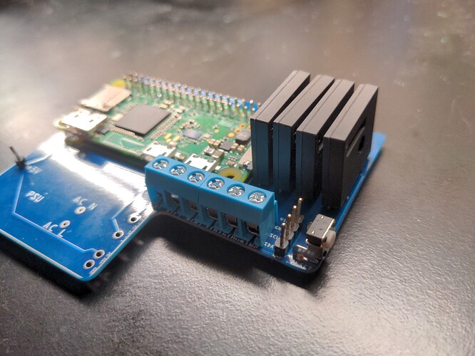
Hereā€™s the almost-finished product:

Thanks goes out to everyone who contributed to this thread. Building a better BOM, together. :slight_smile:

Iā€™m excited to see if it works out for you. Are those the same relays I linked? I never got to the point where I could verify that they worked with the hestia. If the connector works for you, and the relays work, I may just finish my hestia!

Thanks for taking this search where I left off. To be honest I was getting pretty demotivated.

Hey peeps.
I found that this model ( 77313-852-16LF ) Should be good for the screen header (15mm total).
Here is a Canadian site for it: https://www.digikey.ca/en/products/detail/amphenol-icc-fci/77313-852-16LF/4405070

I would love to compile a bit of a stronger list on the BOM page of Hestia Pi, as sourcing some of this stuff is not as easy as searching the part for those who know nothing about the industry, or making. :stuck_out_tongue:
I am brand new to 3D printing, Soldiering, and searching for the materials, but its been fun. :slight_smile: