so yours works, its just delayed? Unlike @hestia_hacker who cant seem to get the relays to trip at all?
ok! i finally took teh time to order that other pin header block, and today installed it in place of the connector I had on there. It works! case fits with the display now!
So now I just need to know one thing, is this thing actually going to work? I have a 24vac power brick that I can power it with. It comes on, it’s what I was doing my initial testing with. How do I test for certain if the relays are working without actually installing it in place of one of my thermostats? I’m guessing I just measure across some terminals on the terminal block, no? If so, what am I measuring, and from where to where?
Thanks! once I know if the relays are working, I can get on to the same testing that others here are reporting.
Well done!
The relays, as they are solid state, control only AC voltages, so connect your 24V AC power accordingly:
and use a voltmeter on the AC mode between C and each contact under test.
So, if youre shopping for parts, this list is accurate except for the display connector. instead buy two of these:
https://www.digikey.com/en/products/detail/amphenol-icc-fci/77313-852-16LF/4405070
and cut one of them down to 10 pins, solder them in next to each other to get your 26 pins for the display.
ill be testing the relays shortly.
Ok, so again, not connected to my actual heating system yet, but i have my 24v transformer connected to C and R, and this powers up the hestia. It comes up, ive already got it configured for wifi and whatnot, thats all good to go. Touch screen works and shows me the current temperature and things. As far as I can tell, the system is up and functional.
If i set to temperature high, the display shows me that heating is on by flashing the little fire icon. At this point i shuld be able to measure across R and W right? Even if nothing is connected to W? If so, something is not working, as I see nothing across R and W, or R and anything else for that matter (except for C of course, R and C show me 24vac).
Nope ![]()
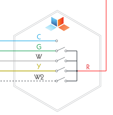
Pay attention to the 4 switches above, representing the relays.
R and W are sorted when the heating is on. But W and C on the other hand will give you 24V AC when ON and 0V when OFF. Same applies for G, Y and W2 (all with C respectively). Forget R for this test
so… really what i should look for in continuity between R and W right? which would mean the relay has been switched on for heat. Right? If thats the case, then it is in fact working.
Just edited my previous post…sorry for the confusion.
Im not sure about continuity as it is not a traditional relay.
Thanks! So, two things.
-
that worked. Between C and whatever ive switched on, i get 24v. Yaay!
-
Continuity between R and whatever I switched on also seems to work. Or, rather resistance, as that’s what the meter i have on hand is able to measure. I get infinite (no reading) between R and any terminal that is not switched on, and I get about 9K ohms from R to whatever terminal i’ve switched on. Whether 9K ohms sounds right or not i have no idea, i sort of expected minimal resistance there, but shrug. Its definitely changing the state of the relay when i switch on heading/fan/cooling. And its doing it immediately. Which contradicts a lot of the other findings in this thread!
At any rate, i feel like my hestiapi is working! Now i just need to work out powering it on the wall, as my heating system is only 2 wire.
Thanks!
1 Like
This topic was automatically closed 91 days after the last reply. New replies are no longer allowed.