How to change the screen saving mode

The Iothermostat application puts the display to sleep after several minutes without touching the screen, and wakes up as soon as the screen is touched.

However, the backlight LEDs do not deactivate.

I’ve installed a new WaveShare display which includes the ability to control the backlight via port 18 of the RPI.

waveshare 3.5inch_RPi_LCD_(B)

I’ve tested and succeeded in turning off the backlight completely, so I’d like to replace the sleep mode with my backlight cut-off function,

However, I don’t understand how the existing standby function is activated.
it seems to me that it’s the same implementation as for HestiaPi

Thanks for your explanations

I don’t remember the HestiaPi image ever blanking out the screen. It think that might just be an Iothermostat thing.

However, I still want to try to be helpful. :heart: I believe screen blanking is generally handled by X, and I was able to dig up a post on the Raspberry Pi forums that also suggests this is the case.

If you run xset q from a shell on your pi, it should print out a bunch of information, including things like “prefer blanking” and “timeout”. The person on the rPi forum wrote a script that constantly looks at the output of that command to see when the brightness changes.

That same forum post links to A Primer on Screen Blanking Under Xorg, which I found incredibly helpful in understanding the details of how all this works. Since your LCD requires GPIO to control the backlight, my guess is that the very last line of that page will be your best bet at a minimally hacky solution: make your script to disable the backlight be the screensaver.

What I imagine would be a bash script that is run when the screensaver comes on. It runs the command to kill the backlight and then just goes into an infinite sleep loop. That’d take care of the “off” part, but what about turning it back on?

I’m guessing that when the screen it touched, X will kill the screensaver process. You can use a trap to have a function or command run when your bash script is killed. If you make that command the one to turn the backlight on, it seems like it should work. It’d still be a little janky, but much better than burning CPU power constantly running xset to see if the screen has been blanked out.

This is all off the time of my head and I haven’t tested any of it, so I’ll be interested to hear if it works as I hypothesize.

Let us know how it goes. And I’d be interested to hear your commets on that screen in general. Not being able to turn the backlight off on the HestiaPi is one of the things that people want but the hardware we’re currently using doesn’t do. It’d be cool to have an upgrade for people. Even it the Waveshare is twice the price of the screen we currently use, some people would probably find it to be worth the extra money.

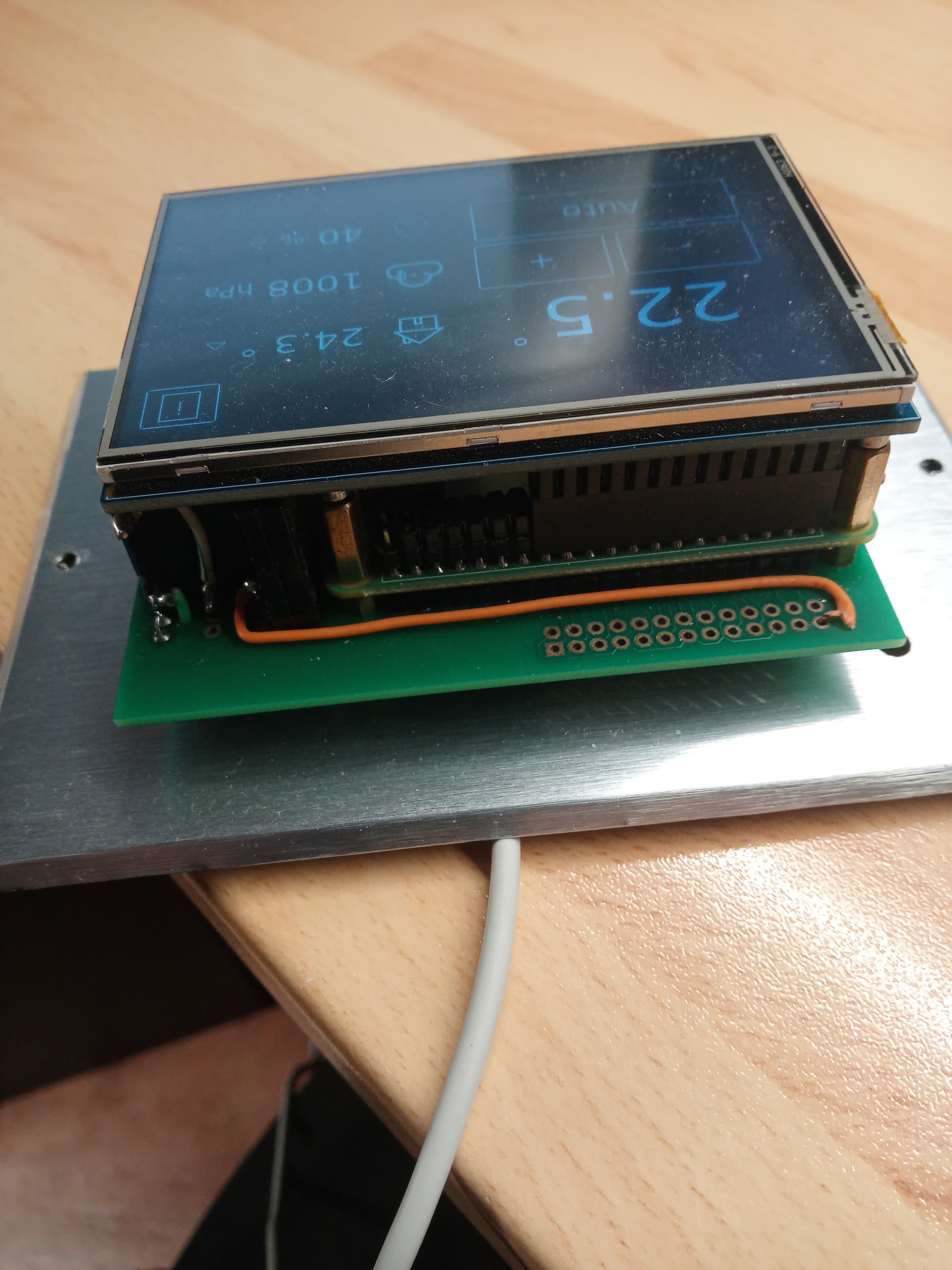
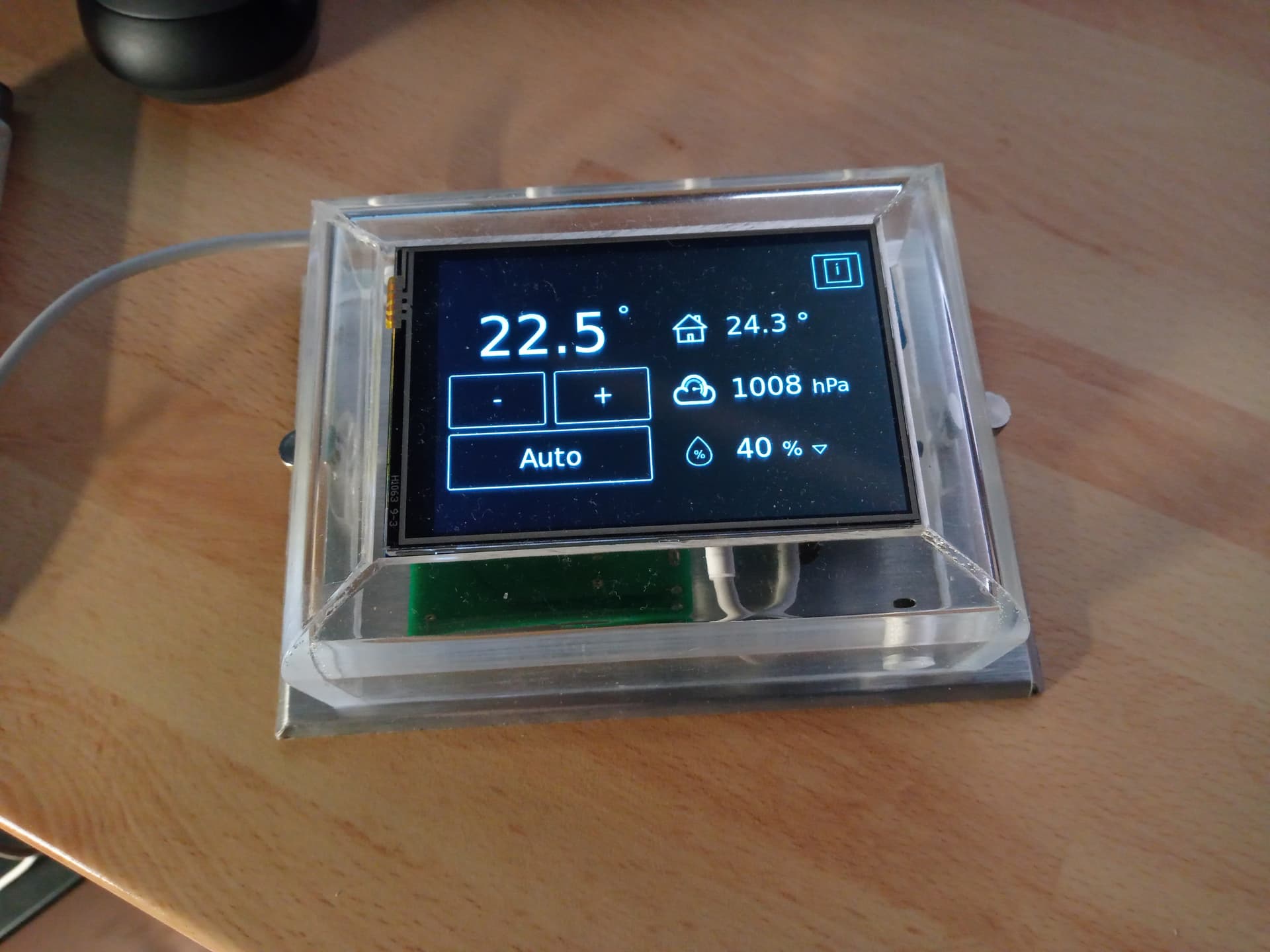
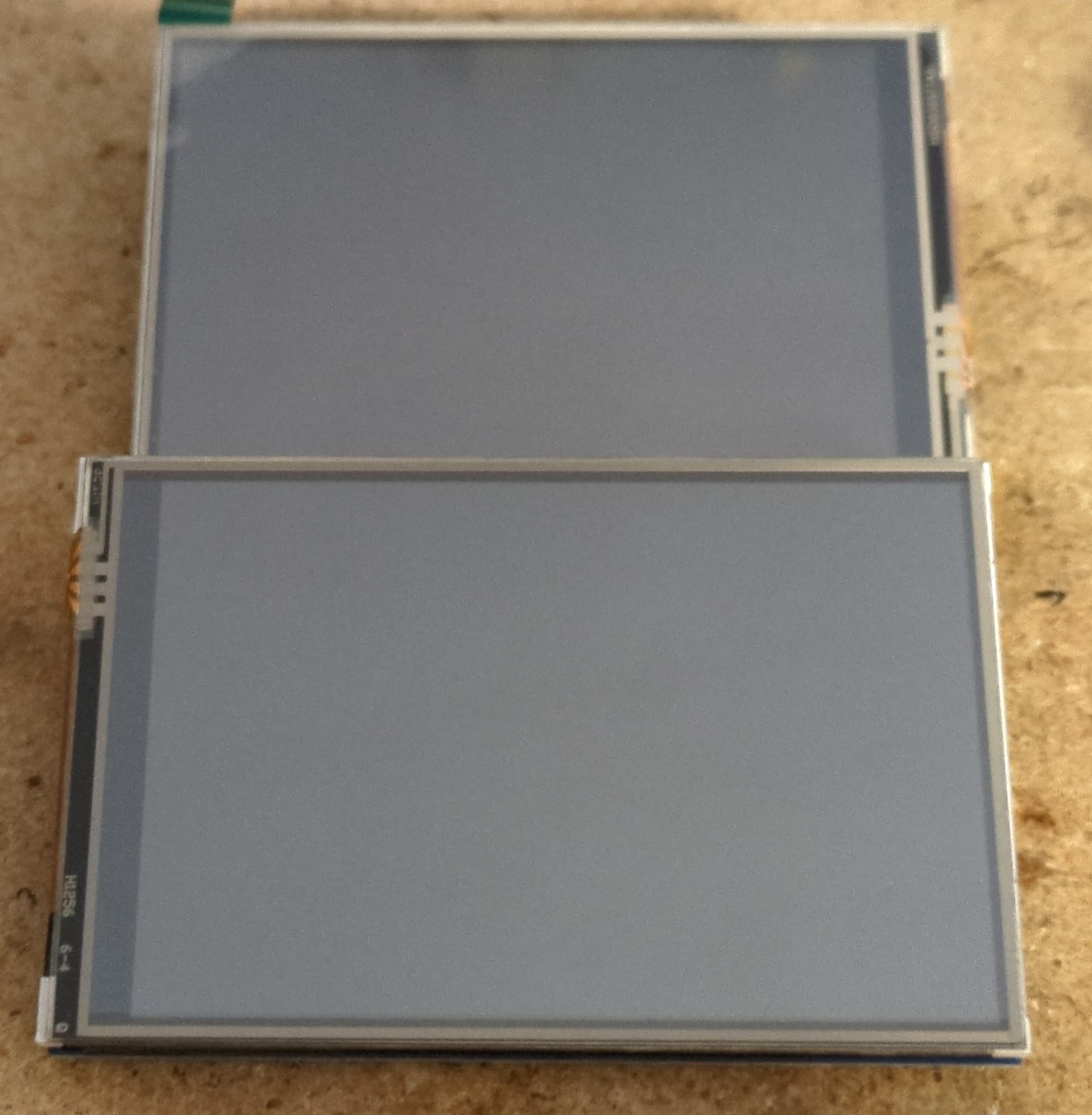
blacklight screen for Iothermostat

Backlight control installation for Waveshare 3.5inch version B screen


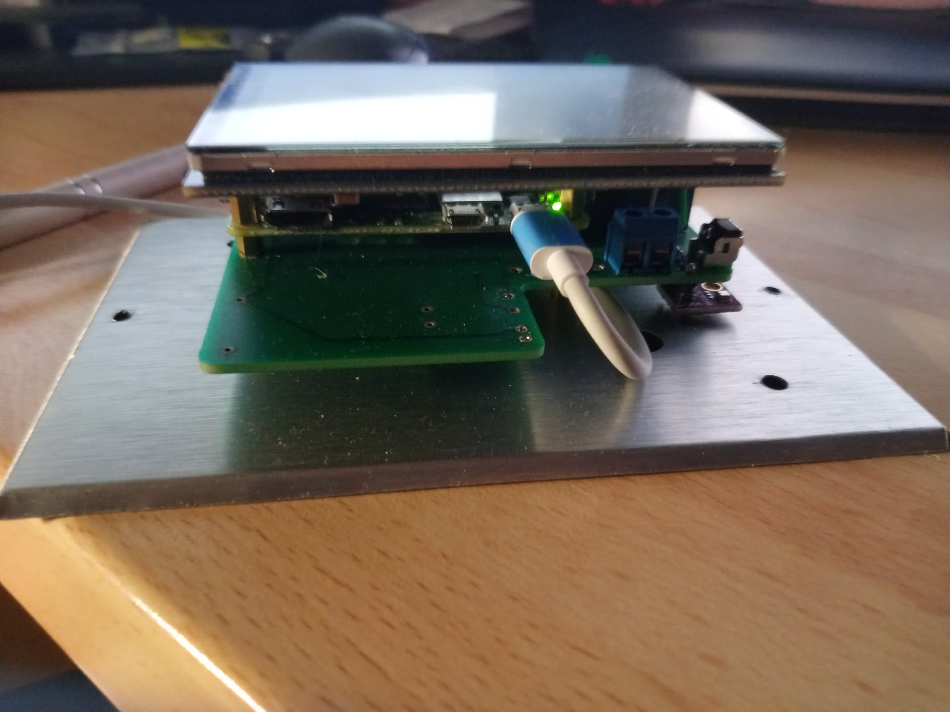
Control is performed via pin12 of the rasp2B 40points connector (gpio18 of the rpi connector) using a pwm command.

but the backlight can be switched off with a value of 0 or fully illuminated with a value of 1.

The iothermostat application works for local display in an X windows session in a simple luakit browser.

Checking the characteristics of the windows manager

iothermostat@iothermostat:~ $ xset q

Keyboard Control:
auto repeat: on key click percent: 0 LED mask: ffffe780

XKB indicators:
00: Caps Lock: off 01: Num Lock: off 02: Scroll Lock: off
03: Compose: off 04: Kana: off 05: Sleep: off
06: Suspend: off 07: Mute: on 08: Misc: on
09: Mail: on 10: Charging: on 11: Shift Lock: off
12: Group 2: off 13: Mouse Keys: on

auto repeat delay: 660 repeat rate: 25

auto repeating keys: 00ffffffdffffbbf
fadfffefffedffff
9fffffffffffff
fff7ffffffffffff

bell percent: 50 bell pitch: 400 bell duration: 100
Pointer Control:
acceleration: 2/1 threshold: 4
Screen Saver:
prefer blanking: yes allow exposures: yes
timeout: 600 cycle: 600

Colors:
default colormap: 0x20 BlackPixel: 0x0 WhitePixel: 0xffff

Font Path:
/usr/share/fonts/X11/misc,built-ins

DPMS (Energy Star):
Standby: 600 Suspend: 600 Off: 600

DPMS is Enabled
Monitor is Off

DPMS management is enabled for the display, but no hardware interface is processed by the device.

#### Backlight control check

GPIO programming: use of sysfs interface (present in app)

see https://www.ics.com/blog/gpio-programming-using-sysfs-interface

https://elinux.org/RPi_GPIO_Code_Samples

user connection iothermostat ( iothermostat must be in the gpio group )

iothermostat@iothermostat:~ $ ls /sys/class/gpio/ export gpiochip0 unexport

create access to gpio18

$ echo 18 >/sys/class/gpio/export
$ ls /sys/class/gpio export gpio18 gpiochip0 unexport
$ ls /sys/class/gpio/gpio18 active_low device direction edge power subsystem uevent value

now we need to define the output
$ echo out >/sys/class/gpio/gpio18/direction

then set the gpio port output value to 1
$ echo 1 >/sys/class/gpio/gpio18/value

Backlighting is now controllable

We’ll see that we can use the raspi-gpio library present in the configuration.

Implementation


Solution 1 modify DPMS management for the display

I haven’t been able to find a solution for processing DPMS to take the display into account.

Solution 2 control display according to DPMS control status

DPMS (Energy Star):
Standby: 600 Suspend: 600 Off: 600
DPMS is Enabled
Monitor is Off

Proposed here Controlling the LCD Backlight, I retain the bash script solution

(simple, no compilation required, and raspi-gpio library installed)

Bash script: backlight.sh

#!/bin/bash
#PWM_PIN=31
PIN=18
# Set pins as output
#raspi-gpio set $PWM_PIN op
raspi-gpio set $PIN op
# Start with both pins HIGH.* *If either of the
# pins go LOW, the backlight will turn off.
#raspi-gpio set $PWM_PIN dh
raspi-gpio set $PIN dh
# Get the current state
CURRENT_STATUS=$(xset q | grep “Monitor is” | awk '{print $3}')
LAST_STATUS=$CURRENT_STATUS
logger -p info -t “backlight_service” -s “Monitor is $CURRENT_STATUS”
# Loop indefinitely updating backlight in sync with monitor status
while true; do
# Check the current monitor status
CURRENT_STATUS=$(xset q | grep “Monitor is” | awk '{print $3}')
# Only turn the backlight on/off if the Monitor state has changed
if [ “$CURRENT_STATUS” != “$LAST_STATUS” ]; then
logger -p info -t “backlight_service” -s “Monitor is $CURRENT_STATUS”
# Control backlight pin according to the monitor status
if [ “$CURRENT_STATUS” = “On” ]; then
logger -p info -t “backlight_service” -s “Turning Backlight On”
raspi-gpio set $PIN dh
else
logger -p info -t “backlight_service” -s “Turning Backlight Off”
raspi-gpio set $PIN dl
fi
LAST_STATUS=$CURRENT_STATUS
fi
# Sleep before checking again
sleep 1s
done

#### integration in iothermostat app

iothermostat@iothermostat:~ $ pstree -a

systemd splash

│ ....
│
├─login -f
│ └─startx /usr/bin/startx -- -nocursor
│ └─xinit /home/iothermostat/.xinitrc -- /usr/bin/X :0 -nocursor vt1 -keeptty -auth /tmp/serverauth.Hz4MUFRc4L
│ ├─Xorg :0 -nocursor vt1 -keeptty -auth /tmp/serverauth.Hz4MUFRc4L
│ │ └─9*[{Xorg}]
│ └─sh /home/iothermostat/.xinitrc
│ ├─backlight.sh ./backlight.sh
│ ├─luakit -u http://localhost/iothermostat/index.php
│ │ ├─WebKitNetworkPr 4 16
│ │ └─11*[{WebKitNetworkPr}]
│ │ ├─WebKitWebProces 9 23
│ │ └─10*[{WebKitWebProces}]
│ │ └─18*[{luakit}]
│ └─matchbox-window
├─

spot controls DPMS status and turns backlight on or off accordingly

http://comfilewiki.co.kr/en/doku.php?id=comfilepi:configure_a_program_to_auto-start:index#configure_an_x_program_to_auto-start_eg_mono

In our case, it will be launched by xinitrc

root@iothermostat:/home/iothermostat# cat /home/iothermostat/.xinitrc

#!/bin/bash
FILE=~/calibrated
/usr/bin/matchbox-window-manager &
if [ -f “$FILE” ]; then
CURRENT_STATUS=$(xset q | grep “Monitor is” | awk '{print $3}')
logger -p info -t “backlight_service” -s “start Monitor is $CURRENT_STATUS”
   ./backlight.sh &
   luakit -u http://localhost/iothermostat/index.php
else
  xinput_calibrator
  touch “$FILE”
fi

### Complements

http://comfilewiki.co.kr/en/doku.php?id=comfilepi:controlling_the_lcd_backlight:index

depending on bash options, double quotes may have to be replaced by single quotes

" must be replace with simple quote

Did you have to mess around with drivers, or were you able to run the bash script and have it work of the stock v1.4 image?

No, I didn’t have to intervene in the original code concerning the drivers or even the application.

The principle is to monitor the DPMS triggering of the screen saver and then switch the backlight on or off, as proposed on this model.

Principle probably applicable to the original hestiaPI

I’m trying to reproduce your work and I’m very confused as to how you accomplished this with the HestiaPi hardware (as in, the PCB with the relays, etc.). At the core, it comes down to how GPIO18 can be used for controlling the screen brightness when it is not wired to the LCD. I’ll try to step through these one point at a time.

So this one is interesting. The Waveshare documentation you linked to clearly shows GPIO 18 controlling the LCD brightness. And the raspberry pi documentation confirms that pin12 is GPIO18.

However, the Waveshare documentation says that pin 12 is not connected!

On the HestiaPi hardware, GPIO 18 is connected to relay 3. It is not connected to the headers that the LCD screen plugs into.

I bought a Waveshare that has backlight control (3.5inch RPi LCD (C)) and soldered the pads on the back per the manufacturers instructions. After this the backlight no longer came on when it was plugged into the HestiaPi PCB. If pin 12 (GPIO 18) controls the backlight, it makes perfect sense that it wouldn’t have any backlight.

If I plug the LCD screen directly into the pi, the screen come on for the first part of the boot and then after a few seconds of loading the software, it turns off the backlight. Again, if GPIO18 is controlling the backlight, this makes sense, as OpenHAB would be initializing that pin to zero to make sure the relay is open.

So all this leads me to believe that the Waveshare pinout is incorrect. Pin 12 does do something, at least when those pads on the back are connected. I also do not understand how this screen could be compatible with the HestiaPi hardware, given that GPIO 18 is not connected to the screen.

Everything else makes sense. The script you put together, the DPMS settings, etc. I’m just confused about how you were able to get the screen shutoff to work with the HestiaPi PCB. Can you help shed some light on this?

hi
first and foremost :
I checked the order

  • if pin 12 of the connector is at 0, then the backlight leds are off, so the screen remains dark
  • if pin 12 of the connector is at 1 (~3.3v) then the leds are lit and hestia information is visible.

now what have i done in particular?

  • install a soldering point as per the doc
  • installation of waveshare Version 2 driver
    (initial problem with orientaion and invert touchscreen)
  • then the programs indicated in my doc.

however, my assembly differs slightly from the standard hestia

the raspberrypi-2-W is of course in the same place, but the screen is connected directly to the raspberry and not to the extension connector

in addition, I’ve added a mechanical relay instead of a solid-state relay (see orange strap and background relay) and not using included power-adaptator, the raspberry is powered by USB power supply


courage :slight_smile:
in its box

That all makes perfect sense now. You must be using a different GPIO pin to control your relay, which would free up GPIO18 to be used to control the LCD’s backlight.

Making this modification to an existing HestiaPi when using the separate LCD headers would require:

  1. cutting the trace on the PCB that connects pin 12 on the pi to pin 12 on the LCD header
  2. soldering a jumper to connect pin 12 on the pi to relay 3 (if you want to use that relay)
  3. soldering a jumper to connect some other GPIO pin (e.g. GPIO15 (pin 10)) to pin 12 on the LCD
  4. put your script on their SD card, but change the GPIO pin used to control the brightness

It’s quite the modification, and I haven’t tested this yet, but it should work. When I find time to test it out, I’ll post back here to share my findings.

Thanks for sharing. This is something that I know some people wanted and it’d be cool to have instructions on how to make it happen. After all, open source hardware is supposed to be hackable (in the good way :smiley:).