Is there a version of the schematic in something relatively standard, like PDF or EPS? All I find is some Fritzing thing that wants me to pay US$12 for it.
As far as I know that’s the only official EDA files of the HestiaPi ONE. There’s an older, two relay model, that was made in KiCAD here:
But that’s not the HestiaPi ONE. I’ve never built one of those. That was from before I started contributing to the project.
I have some KiCAD models that I made in an attempt to re-create the board in KiCAD, but I’m afraid I haven’t done a good job at versioning them and so I don’t have the originals anymore. At this point all I have is an versions that are either incorrect or experimental and untested.
I’ve uploaded the one that I am using now (which I’m calling v2.5). I tried swapping out the reset button for a power switch because the Raspberry Pi Zero 2 W boards don’t have a reset pin anymore. They now have a reset pad, which is not nearly as useful. The problem is that I selected a switch that couldn’t handle the current draw of a Pi Zero 2. So you have to jumper the center hole of the switch to the hole to either side. If you want to reboot, you have to flip the breaker to the HVAC.
I have a later model which has a different switch, and a ribbon cable instead of the extra long headers that are difficult for new users to line up and snap on the case to the backplate. The problem is that these are not completely tested. I don’t like sharing untested (and thus, possibly incomplete) models, so I’d like to wait before releasing those.
I should also stress that the boards I created are unofficial. They haven’t been reviewed or accepted by… well anyone, let alone the project creator. Furthermore, they haven’t been tested with any European 240V systems, like… at all. If all that doesn’t scare you away, you should be able to export the .kicad_sch file to a PDF. The v2.5 schematic should be fine, so long as you don’t use the model of switch that the files call for.
I’m just trying to troubleshoot some weirdness on one of the relays. I replaced it, and it still doesn’t work. I checked the inputs to relay, and it’s very strange: -1.4V all the time. When I check the leg going to the GPIO it looks reasonable, it’s the other leg that is showing -1.4V. All the other relays show 0V on that side, which is what I would expect if the circuit was GPIO->Relay±>Relay- ->Gnd.
So, I want a schematic so I understand what that circuit is supposed to look like. Maybe something funny has happened on an inner layer of the carrier board.
I also want to troubleshoot the I2C - I got the new sensor, and it also does not work, so I looked at the signal lines when the sensor was not connected, and I see the data line toggling, but clock is stuck at 0V. Again, I want to see if there is something other than a simple connection to the GPIO there.
I think the easiest to read place to get that information would be section 7.3.1 of the owner’s manual. This shows which relays are connected to which GPIO pins and the same for the I2C as well.
This is also on the wiki, which also has an illustration of the pi to let you determine which pin is which.
It sounds like you have a pretty good workbench, so I’d say start with connecting the LCD screen and I2C chip directly to the pi. That will allow you to test the sensor by itself without the HestiaPi PCB being in the picture.
The datasheet for the relay labels the two load pints (the ones further apart) as 1 and 2 while the input pins (the ones close together) are 3 and 4. Pin 4 goes to ground, and pin 3 goes to a GPIO. On the load side, pin 2 is hot (+24V AC) and pin 1 is neutral.
And I know the output rating says the load voltage range is 75-264V AC, but I can attest that they do work with 24V AC in practice.
The schematic on Github is wrong - it shows the relays being driven by a standard common-emitter NPN with snap-back diode, whereas in fact they are driven directly by the GPIO and no snap-back (unneeded since the input is a LED, not a coil).
I had assumed (and we all know about ass-u-me) that all the connections from the Pi to the carrier board were OK - but this caused me to question that, and to find that in fact that connection was open. A bit of reflowing later and the connections all check out - all the relays and the I2C data and clock. So, now to boot and check.
And the temp sensor is working.
1 Like
Can you help us fix this? I’m not sure if you’re referencing the wiki (which has a table showing which relays are connected to which GPIOs and which physical pins) or something else that is on GitHub.
I’m referring to the schematic you said you were working on:
Are we looking at the same file? hestia-touch-pcb-dev/HestiaPi-ONE/KiCAD/HestiaPiOneUniversal.kicad_sch
Here’s what I see (GPIO12 highlighted to show the connection directly to the solid state relay).
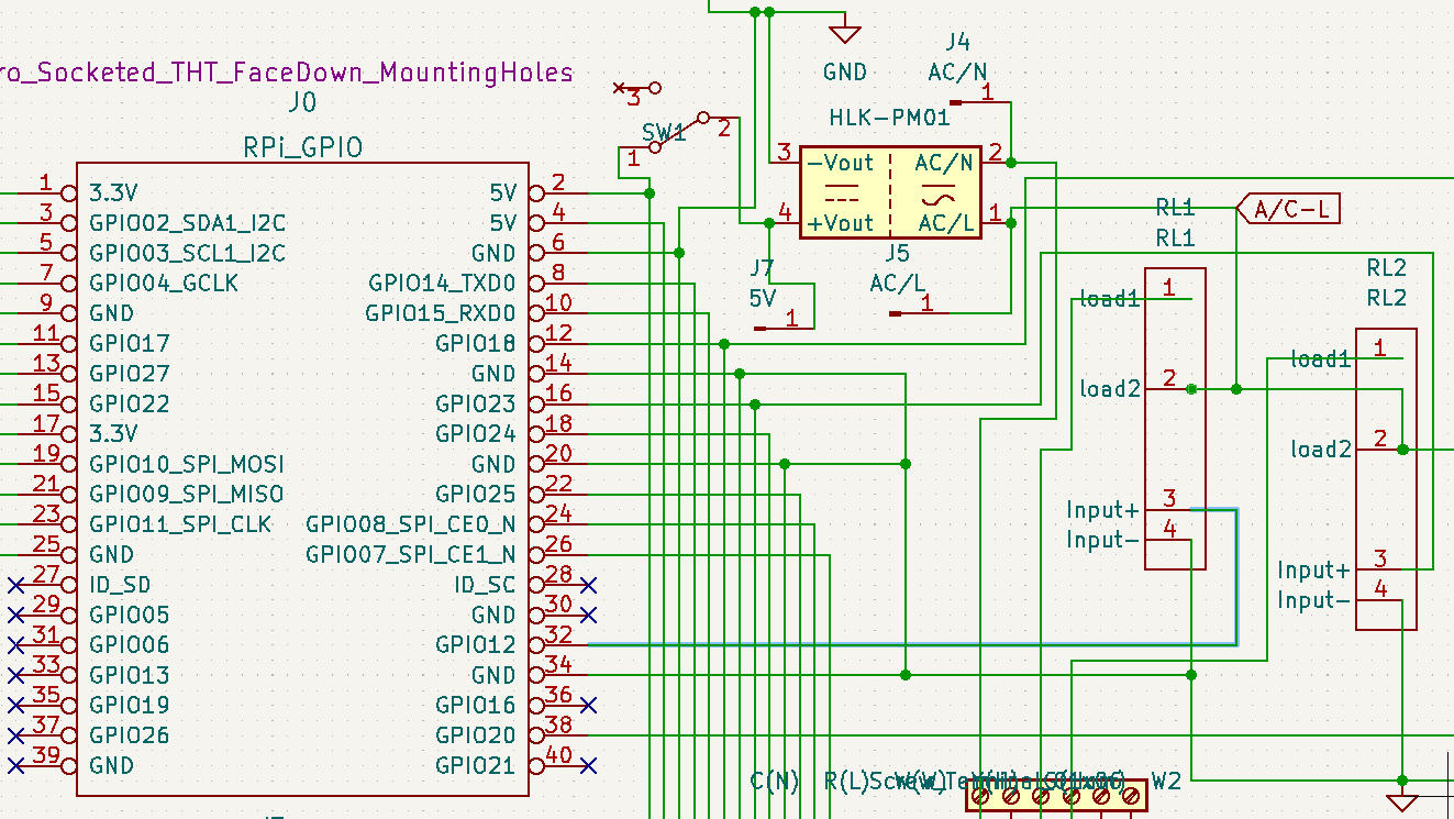
I also added a PDF of the schematic to that repo just now to make it viewable without needing KiCAD installed.
I cloned the project from GitHub, and looked at:
hestia-touch-pcb-dev/HestiaPi-KiCAD/HestiaPi-KiCAD.sch
Ah, that schematic is for a different model of Hestia Pi, a model that predated the HestiaPi ONE.