Touchscreen not working with cover on?

I bought a kit on Tindie and have just gotten around to putting it together. I am running in a test mode (not hooked up to my US HVAC).

I am having problems with the touchscreen not responding. I downloaded the driver from this site as directed and installed it on v1.3-dev. It shows the interface, but does not respond to touch. I downloaded a test system image from the display web site and ran it without the front cover and it worked for touch. I then booted for my HestiaPi system image disk without installing the front cover and it worked. When I install the front cover, the touchscreen stops working! I have checked the pin alignment to make sure I am installing the screen correctly. Could the cover be touching the screen and preventing sensing the touch input?

@hestia_hacker is your contact person as this is not manufactured or sold by HestiaPi but by them as an individual.

Hello. :wave: I haven’t seen the case interfere with using the touch screen, but it sounds like that’s exactly what you are facing.

It’s a resistive touch screen, so my hypothesis is that the screen is reading a constant button presses and thus ignoring the actual button presses. To test this and see how we can get it resolved, I’d like to ask a few questions and test a few things.

  1. What case are you using? I’ve been testing with the BaseONESnap2HNuts.stl and CoverOneSnap2H.stl file from GitHub - HestiaPi/hestia-touch-case: 3D printable case for the HestiaPi Touch model The older files have some alignment issue.
  2. Does it seem like the tabs that hold the LCD in place are pinching the screen tightly? I’m not sure how to objectively measure this pressure, but when you go to remove the screen from the case, the screen should slide over without too much pressure.
  3. Try installing just the front cover and not putting the back on. Obviously omitting the back plate isn’t an option for when it is installed on the wall, but testing this on the bench might allow us to determine where the problem lies so we can get it resolved.

Hopefully these tests will help us determine where the issue lies and we can figure out how to solve it. Once it’s resolved, I’ll make sure to update the documentation to warn people of whatever is causing the issue.

Thanks for you response. I purchased the case from you on April 27, 2023, Order Number: 390458, so I do not know which 3D printed case I have. Maybe you can tell me for future reference.

I tried #3, and installed the front cover without the back plate and the touchscreen works as it should. So the tabs are not the problem.

I will try to install with the entire case and pay attention to the pressure on the screen before I boot the Pi.

Sorry for the delay in responding. I am very busy and this is just a hobby (Raspberry Pi and IoT). I am very interested in getting this working to replace my dumb Honeywell Home thermostat!

Thanks again!

Glad to see you were able to run the test and report back. You do have the latest case design ( specifically: the aforementioned BaseONESnap2HNuts.stl and CoverOneSnap2H.stl files)

If the case is pushing on the LCD screen as we suspect, you should be able to just snip the long pins (that connect to the LCD screen) to be just a little bit shorter. If the LCD pins are the longest ones on the back of the board, you could try taking off the excess there first to get it to fit. I usually trim the back of the boards I solder together, which might be why I haven’t seen this on my units.

You can probably get an estimate of how much needs cut by gently pressing down on the LCD screen when putting the case together and seeing how far away the shell is from attaching to the back plate.

I’m not sure what kind of equipment you have access to, but if you have calipers I’d be very interesting in knowing exact measurements of the LCD pins (both from the top of the board and from the back of the board). I’d also want both of these measurements after you snip them. If you don’t have calipers, an estimate would still be helpful. For example, trimmed the top by the thickness of a US nickel, or two dimes, or something like that.

Once we get this resolved, I’ll update the documentation to specify exactly how long these LCD headers should be and what the tolerances are so this can be avoided in the future. I can also move or trim the long headers that I send out in the future to avoid this problem. I apologize for not already having this documented and avoiding this problem that you’re facing. Thank you for taking the time to come here to the forum and let us know so we can do better going forward.

I did some testing with the pin lengths to try to find the shortest mating length that would still be long enough to make contact with the LCD panel.

First, some terminology:

Pins-marked-up-and-cropped

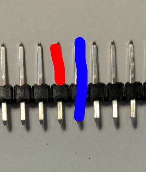
In the image above, the red line is attempting to show the mating length. That is, the length from where the pin comes out of the plastic to the tip.

The blue line is attempting to show the pin length. That’s the entire pin.

In case you are wondering, the term for the bottom segment is the pin tail length. That is from where the pin comes out of the plastic on the bottom to the bottom tip.

With that out of the way, in our case, the important value is the pin length, as that is what could be attempting to hold the case apart, putting pressure on the touchscreen, and causing it to not respond to taps.

I was able to confirm the a pin length of 12mm and a mating length of about 7.5mm still functions.

It also worked for me with what must have had a total pin length of 14.5mm because I measured the mating length and it was 10mm. That is, it fit in the case, the screen showed the UI and the touchscreen worked.

I measured the length of the long headers that I have not installed yet and it’s a 17.5mm pin length and a 12mm mating length. I’ve had to switch manufacturers a couple times due to supply chain issues though, so it’d be worth measuring to confirm you have the exact same measurements on your side.

In case you don’t have calipers, a US nickel is almost exactly 2mm thick. So if you chop two nickels’ worth off the top of your pins, you should be good to go.

On the next unit that I assemble, I’ll try testing it without trimming the tails to see if I can reproduce this issue. If I can, I’ll try to do additional tests with cutting things down to size.

Once we get this sorted out, I’ll make sure to trim all the parts down to size until I can source ones that are shorter, but not too short!

I have also had issues with the responsiveness of the screen, so might need to work through this as well. I figured it was just the underlying hardware not reacting quickly enough, but maybe something more to it?

I was having the same issue and thought I might be running into this. But I removed the screen and board form the case and am still running into responsiveness issues.

I was looking into the screen a bit more to try to find the source of it and it seems like the original screen is supposed to be the Waveshare 3.5inch A or B revision (https://www.waveshare.com/wiki/3.5inch_RPi_LCD_(A) or https://www.waveshare.com/wiki/3.5inch_RPi_LCD_(B)). But the screen I have looks slightly different on the back and may be a clone. I’m wondering if the clones are a bit worse in regards to touch responsiveness and accuracy?

First, let me just make sure we’re on the same page about how responsive the touch screen should be. Here’s a video I just took of me tapping on one the units I have on my lab bench.

This is what I expect in terms of performance. For reference, I’m using the build 6185 image, which is the current candidate to become 1.4-dev.

Waveshare models

The Hosyond brand that I’ve been buying uses the same driver as the Waveshare A version. Looking at the pictures, it looks like it’s the exact same thing, as least on the electronics side, which is where I’d expect any delays to be introduced. A low-quality resistive touch screen would likely either not register clicks or register them in an incorrect location, and a low quality LCD could have poor color balance or contrast, but neither of those should cause slow responsiveness. This is the same chip that was used in the LCD screens that shipped out with the initial crowdfunding campaign.

I suppose a way to test that would be to use the screen with some other Raspberry Pi image that uses the screen to determine if it’s the hardware.

The other screens use different drivers and would not work with a stock HestiaPi image (any version). The B model would probably work by just updating the driver. The C model would may very well require additional changes.

Alternative screens

The Waveshare B version does look different. The product page neglects to mention what chip drives that model, but based on the photos, it looks like it has 1805 printed on it. There’s another number that I can’t quite make out, but it looks like it’s different from the XPT2046. It also uses a different driver, which further supports this theory.

I also noticed that there’s a C version that is the same physical size and resolution, but it’s labeled as “High Speed SPI”. The product page says it’s 125MHz, and according to this post the Raspberry Pi should be able to handle it. Again, it’s another driver for this one and possibly a more involved swap.

If anyone wants to try these other models, I’d be interested in hearing how it works out.

I was able to reproduce this exact problem today while testing an order before shipping it out!

I verified that the tabs that hold the LCD in place were NOT pinching the screen in a way that interfered with the touch operations.

I measured the total pin length (from the backplate to the tip) as 15.5 mm, which was clearly too long. The display worked fine and the case closed, but touches did not register. It’s the exact same issue that @zenga originally reported.

I snipped all the pins to be 13 mm in total length. After that, the touches registered just fine. This matches my previous testing which indicated pin lengths of 12-14.5mm also work correctly.

So now we have a confirmed fix for this issue and measurements for a range which is acceptable.

Going forward, I will make sure to trim any units I build down to size. I will also try to find a different set of pins so I don’t have to trim anything once I get through the current stock.

I’m glad I was able to see this first hand and confirm we understand the issue correctly, as well as verify that the proposed solution is effective.

This topic was automatically closed 91 days after the last reply. New replies are no longer allowed.