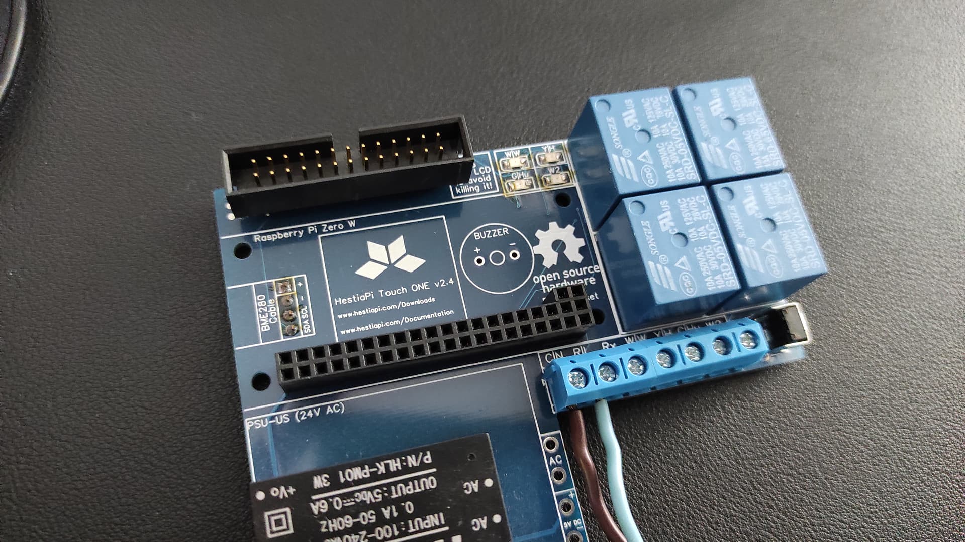
I have attempted to build a clicky edition of the HestiaPi. Overall it went pretty well and I ended up with a working thermostat.
Testing
I was able to test all the relays manually and they work fine, but I was not able to get GPIO16 to turn on with OpenHAB. I boosted everything in Generic (EU) mode and only got the three lights/relays. I switch to HVAC (US) mode, enabled 2nd stage heat with 1 minute delay and 1 degree threshold, and then cranked up the heating set point. The heat turned on, but the 2nd stage never kicked in.
I ended up testing the hardware with echo 1 > /sys/class/gpio/gpio16/value from a root shell. That worked just fine.
Anyone know how can I use the thermostat’s normal controls to test out this relay?
Edit: Apparently I was doing the right thing for second stage heat. It just kicked on now while I am in Generic/EU mode.
LED overlap
The board seems to have been laid out with the assumption that the pi doesn’t have any components that stick out past its PCB.
One of the surface mount LEDs collides with the USB port on the pi.
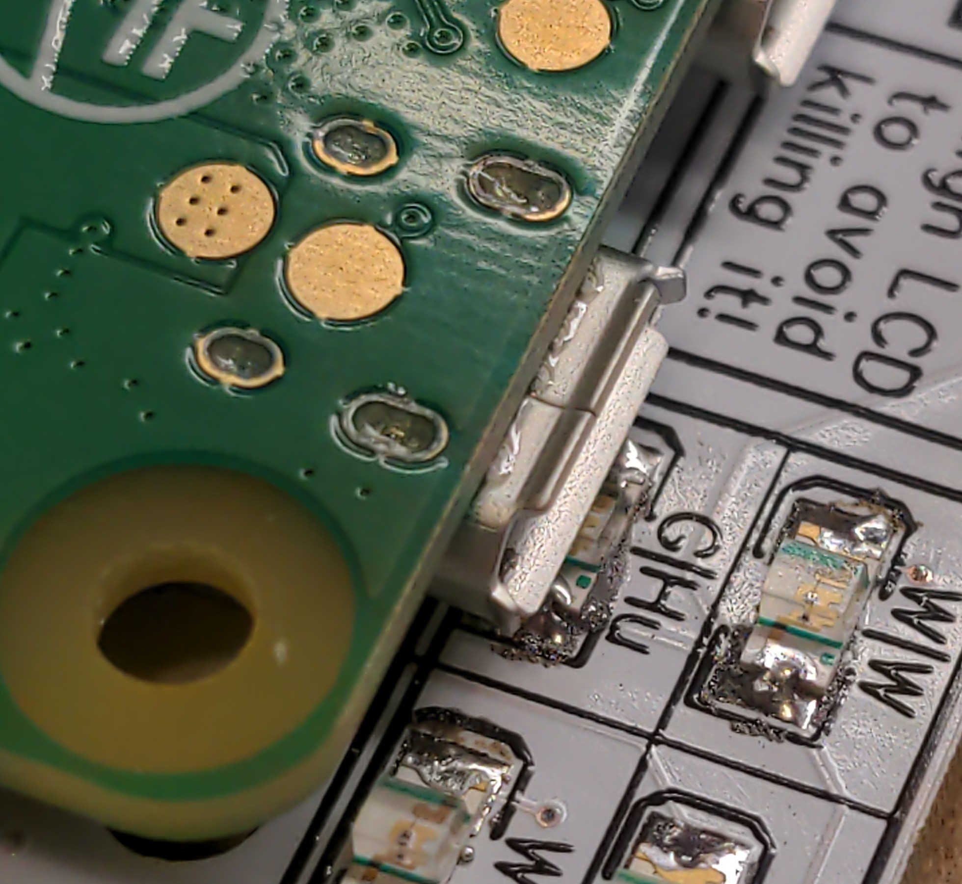
This causes the pi to not sit flat/level.
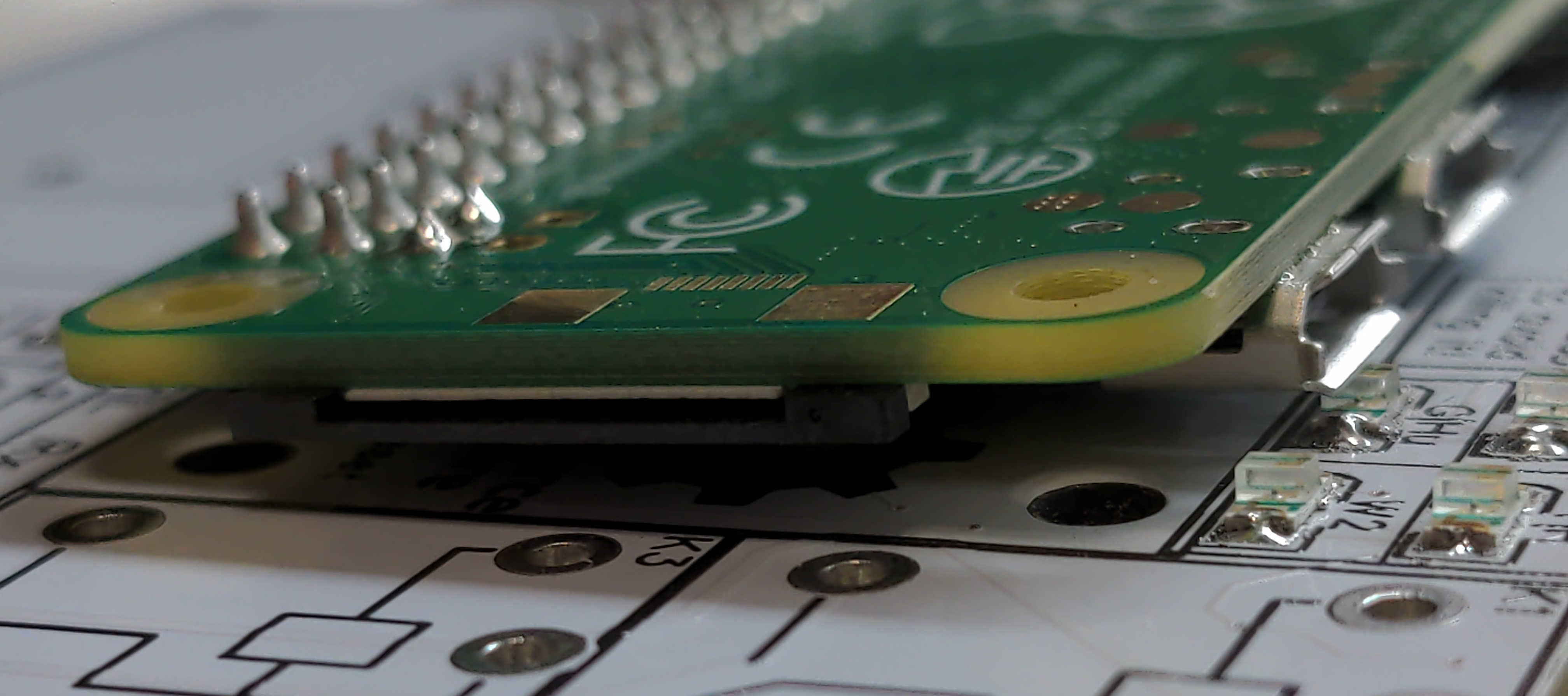
Relay overlap
Next there is the connector for… well I don’t know what, but it sticks out past the end of the pi and into the relay’s airspace. This one is within tolerance though.

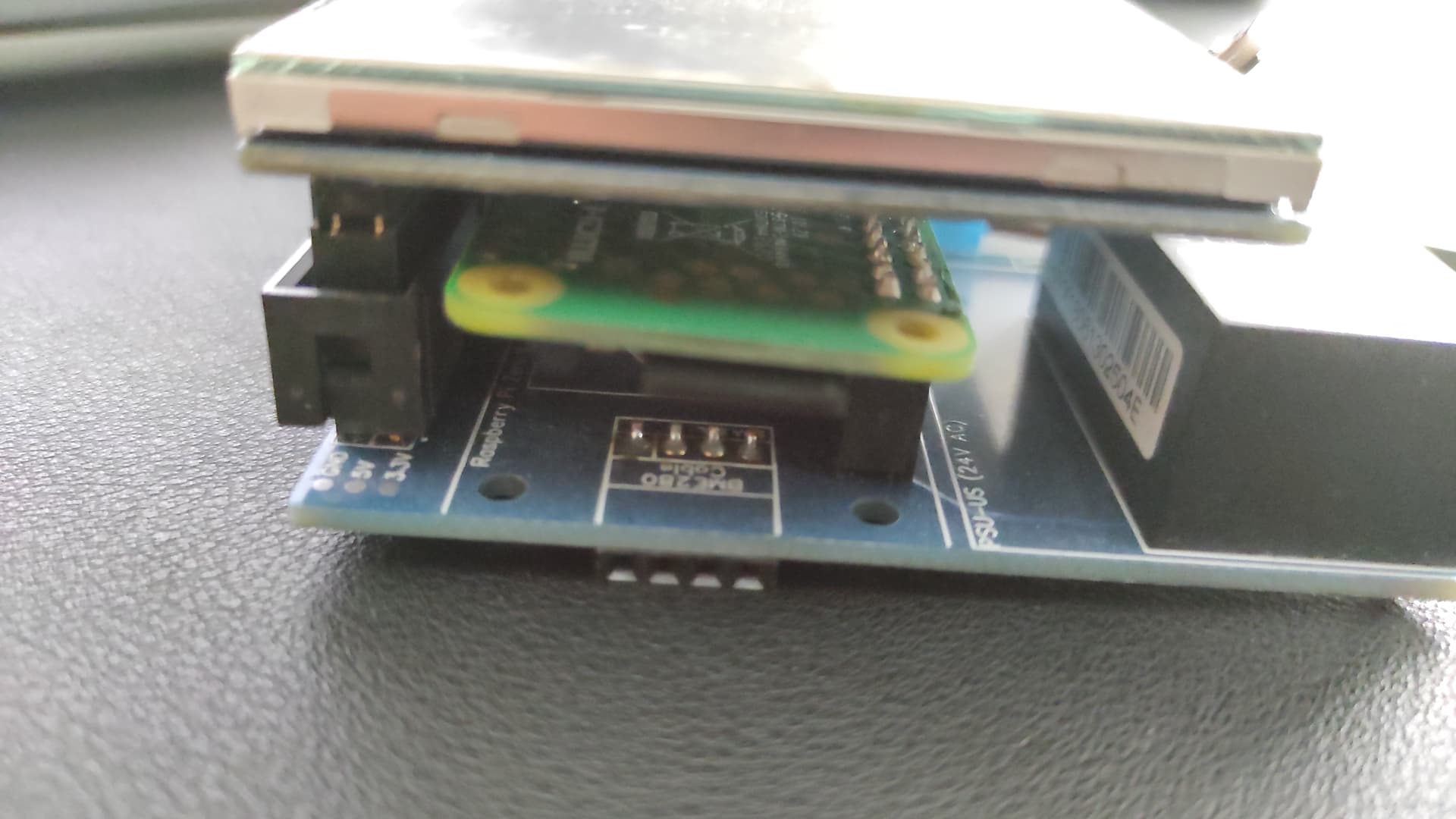
Pi Zero Headers
The other issue is that standard headers (which are sometimes pre-soldered onto pi zeros) are too big and cause the HestiaPi PCB to not sit flat against the case. This just means cutting all 40 of those pins down to size.
If you have a pi that doesn’t have headers already soldered on, you can put the pins in with the excess metal sticking up (away from the wall) instead of down (towards the wall).
Like the relay overlap, it’s not a problem, but something to be aware of and be expecting.
Conclusion
If anyone wants to build one of these, I can attest that they function just fine. If there is a revision on the board, maybe that one LED could be moved to avoid the collision.