By the way, your list was instrumental in helping me get the parts I needed. Only took two weeks to get it all ordered, and found.
Here’s what I got:
- 1 Raspberry Pi Zero W
- 4 G3MC-202P-DC5 relays
- 1 TL1105WF160Q reset switch
- 1 TB003-500-P06BE six post terminal block
- 1 BME280 sensor such as a SEN0372
- 1 cable for BME280 sensor
- 1 touch screen
- 1 2x13 long headers (15mm total length, 12mm head), alternate that requires pulling pins
- AC/DC converter (if powering the unit from the HVAC system)
- PCB can be ordered from JLCPCB
It’s worth noting that I don’t have a completely assembled unit yet. My LCD headers should be in next week and I expect to wrap up.
I’m not sure these (shown in your picture too) are compatible to be driven by the Pi directly. Have you tested them?
Welcome aboard 
You brought this up when I linked them as well. They were offered by… Mouser as a replacement for the relays you had listed in the initial BOM. They are the relays I bought. But I have not been able to test them yet.
Completely untested. LCD headers should arrive Monday and if all goes well, I should have an answer for everyone next weekend.
Why did you use male header for the Pi?
Not that I think your comment was meant to be aggressive, but I was having trouble finding detailed instructions. Similar to the bill of materials list.
Also I didn’t see anything that looked like it would go there or was the proper thing. I didn’t see a male female connector that would replace the male header.

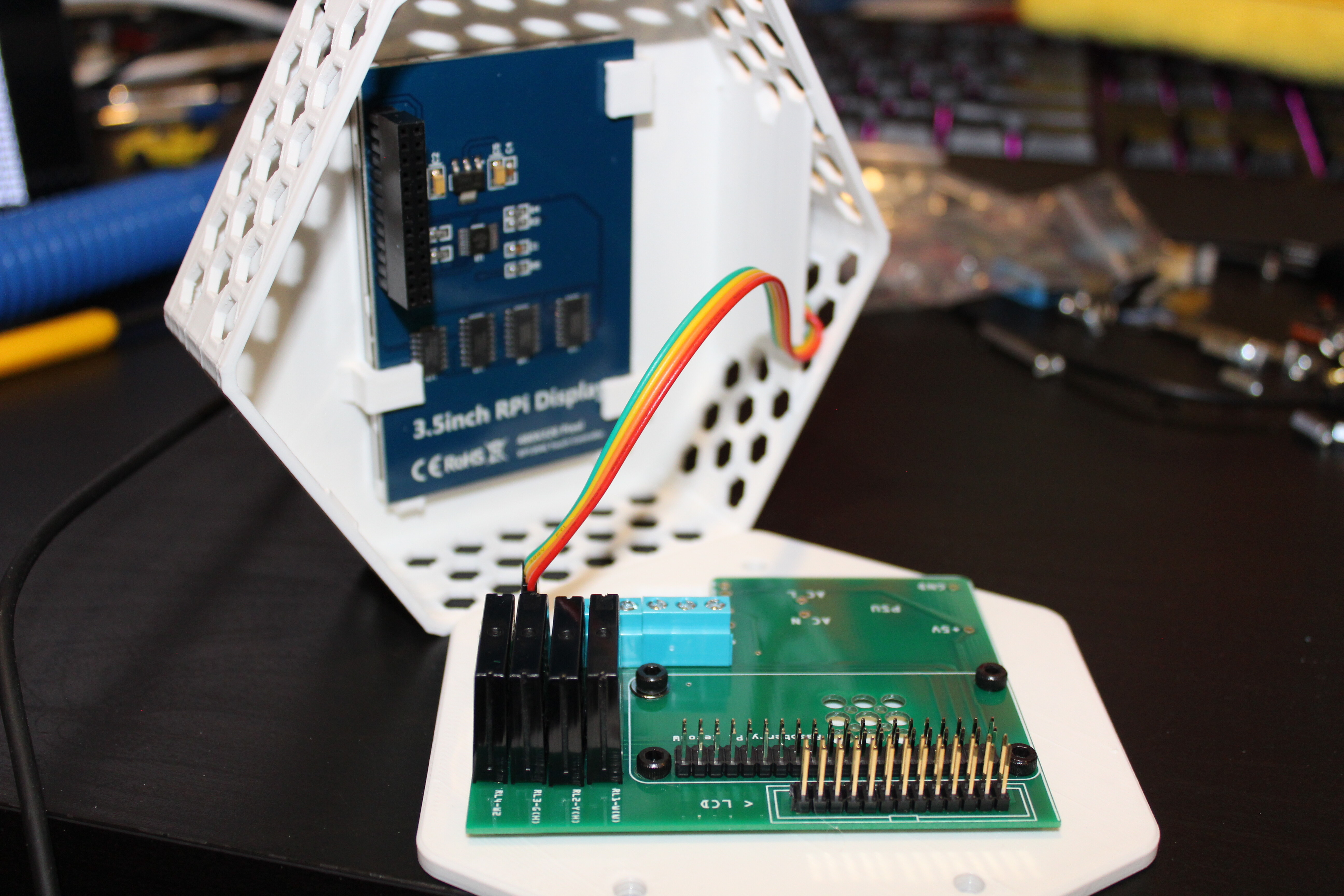
There’s a soldering guide on the site somewhere… It suggests that you take the Pi, and line its existing header pins up with the holes in the PCB . Then from behind you heat up each pin through the hole in the pcb, and fill in with solder. This effectively surface mounts the pi zero to the pcb.
I didnt love it, but I did it, and it worked.
1 Like
The somewhere is the trouble I was having … 
I would definitely much prefer to have a socketable Pi-zero.
And yes, I agree. No offense @HestiaPi but documentation is not great.
1 Like
Youll see once you mount the case, but wit this thing clearance is everything. Ive tried a number of ideas for changing the layout and build to make things a little easier or maybe simpler, but none of them panned out because of the overall fit. I ended up putting it together just like the guide I linked.
1 Like
There’s no such thing as a low profile 26 pin mating header?
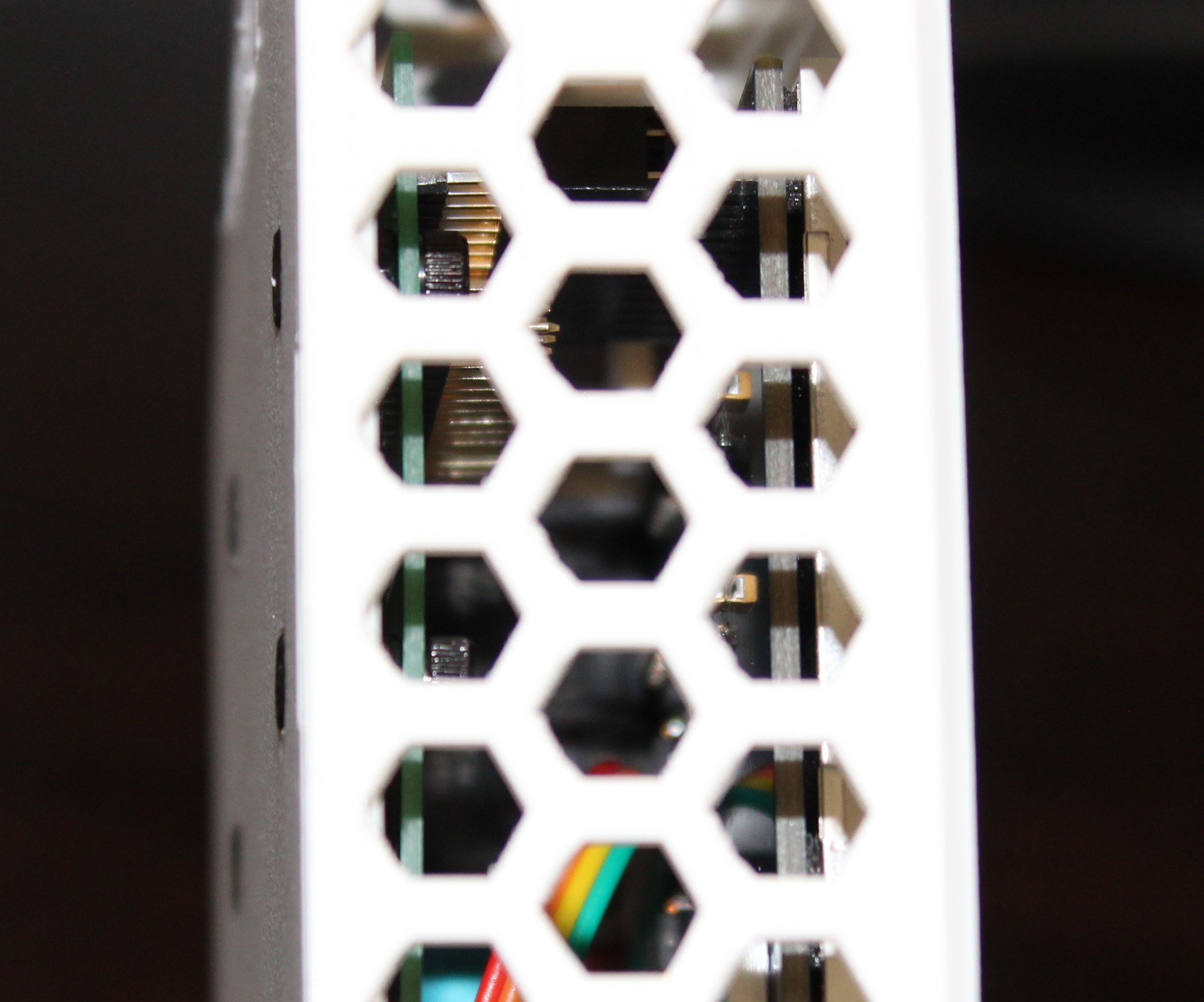
While looking at the device overall, the header that I put in there seems to have lots of space, and looks fine?
What clearance above the Pi-Zero do I need?
The power supply goes to the south of it, and to my knowlege, I do not need to mount anything above it?
I couldn’t agree more ![]() The documentation was always left a bit behind especially when new PCB version were coming up. There is still another one paused due to the pandemic with a socketable Pi to save you from dodgy soldering.
The documentation was always left a bit behind especially when new PCB version were coming up. There is still another one paused due to the pandemic with a socketable Pi to save you from dodgy soldering.
I would love to help with this, or am willing to send some high quality photos once I get it right.
As you can see from my picture here, even with that header, the pins have lots of space.
If its wiring the furnace up that becomes a problem, I think my (accidentally wrong) power supply may help. Hahaha sooo many adventures.
2 Likes
Sorry, I was away on vacation.
I think your method of attaching the pi will be fine, as long as you have stand offs or spacers between the mounting holes and the pcb so that when you put the screws into the back plate to mount it you don’t put stress on the Pi’s board.
The relays are the real clearance nightmare. Which is why the display spacing has to be just right.
Always happy to have more contributors to the docs. I haven’t built my own HestiaPi until now, so the documentation in the manual is just what was copied from the wiki. I have been taking fairly detailed pictures as I go and plan on updating the manual as soon as I have a fully functional unit. That, in combination with photos others have taken, should make for a pretty sweet guide!
The manual also seems like it should contain the BOM as well. Again, this was an oversight on my part on account of having never personally built one and that info was not on the wiki, but rather on the website. We are building up a pretty good list here in this thread, so I plan on using that as a starting point.
As for an update on my build, all the hardware is together and short of needing to reflow any bad joints, it should be done by the end of the day.
1 Like
When I update the manual, I will also be adding troubleshooting information. For example, if the SD card is not properly flashed, you will get a blank screen. If your reset button doesn’t work, check it with a meter and if it doesn’t work, reflow the switch; if it does work, trace back until you find the solder joint that is faulty. (Can you guess what problems I’ve personally run into so far?)
That brings me to my next point, I went through the initial setup, and got it connected to my wifi. Now I am getting booted up, but it is not fully operational. If just says “Off” and clicking the “Off” button has no effect. Clicking the info button in the top right works, so I know it is not a touchscreen issue. The info page is empty though…
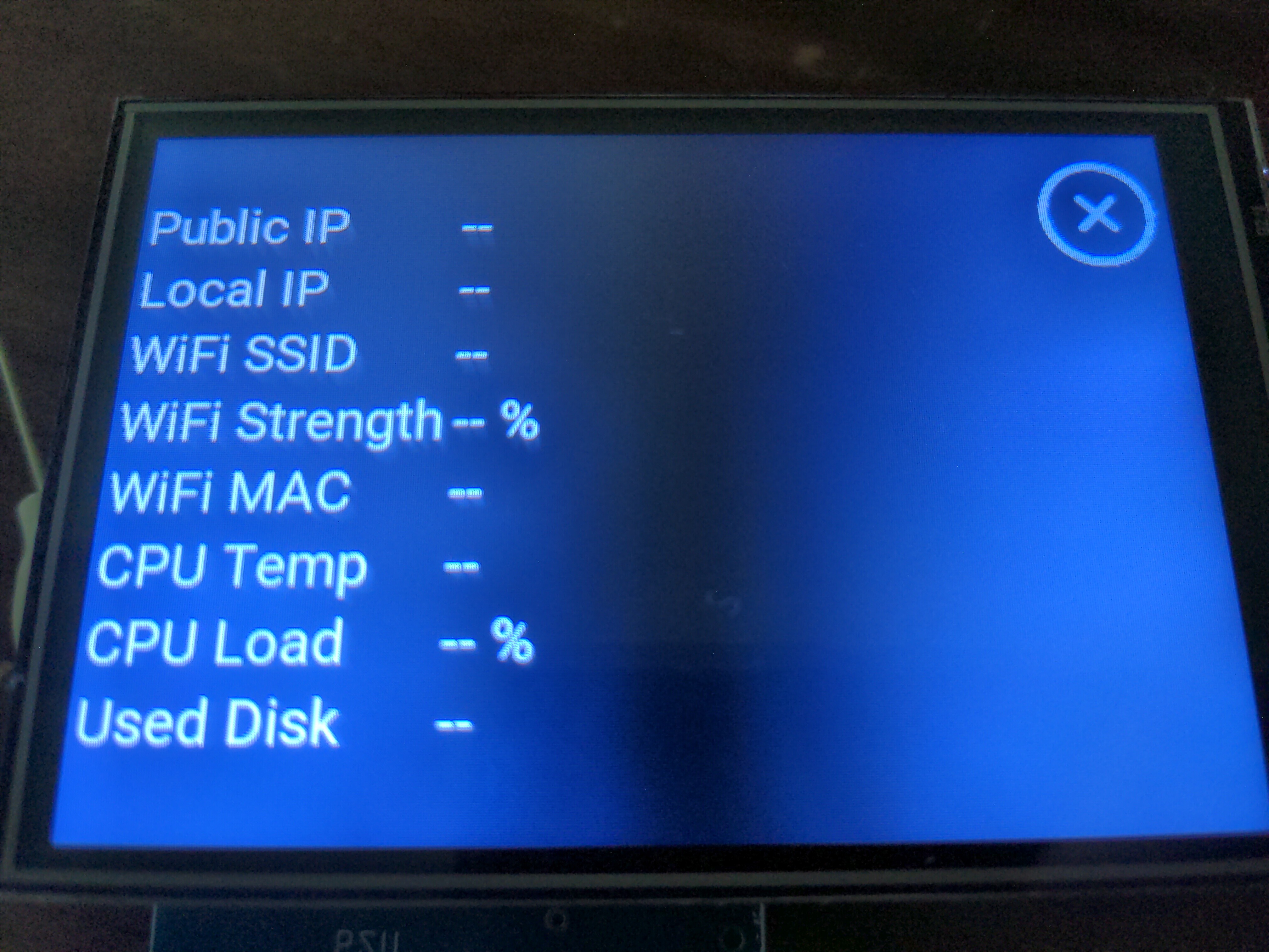
I’ve waited over an hour hoping that maybe it was just being slow and would magically start working. It did not. Any ideas on what this might be? I tried rebooting, just in case that’d help, but no dice. Any ideas on easy ways to troubleshoot this? I can try port scanning my network to find it and SSHing in, but if it really doesn’t have an IP address, that’s obviously not going to work. If it is getting an address, then I feel like this is a bug that it is not showing up on the info page.
I assume you connected initially to the WiFi network HESTIAPI and entered your home’s WiFi credentials which would trigger a reboot, right? Some times we have noticed that after the reboot if your try to access the webpage before the LCD is fully loaded, it can cause some issues and block the proper initialisation of the OH setup. This is only for the first boot. Try reflashing the SD to be sure nothing wrong is left behind.
1 Like