I have jut received my HestiaPI kit.
I live in Italy, so the power line is 220 Volts, but the boiler is controlled by 2 wire where is present a 24volts dc tension.
My old thermostatan just close the contact to give the command to switch on the boiler.
I believe that may be a more flexible that HetiaPI board export the two contact of the relè. Decoupling the power supply of the HestiaPI and the way who control the device all become more flexible.
Hey Sergio! Welcome to the club!
That is indeed a more flexible approach we have heard again from another Italian member of the community.
It will however need, for the rest of the people, a loop wire between the “power in” to the “relay in” contact.
Maybe if we do offer the 2 terminals on the PCB but connect them with a copper track that people can cut with a knife if they need the decoupled scenario you describe…
We always try to keep our design open to more people without adding too much complexity for the majority.
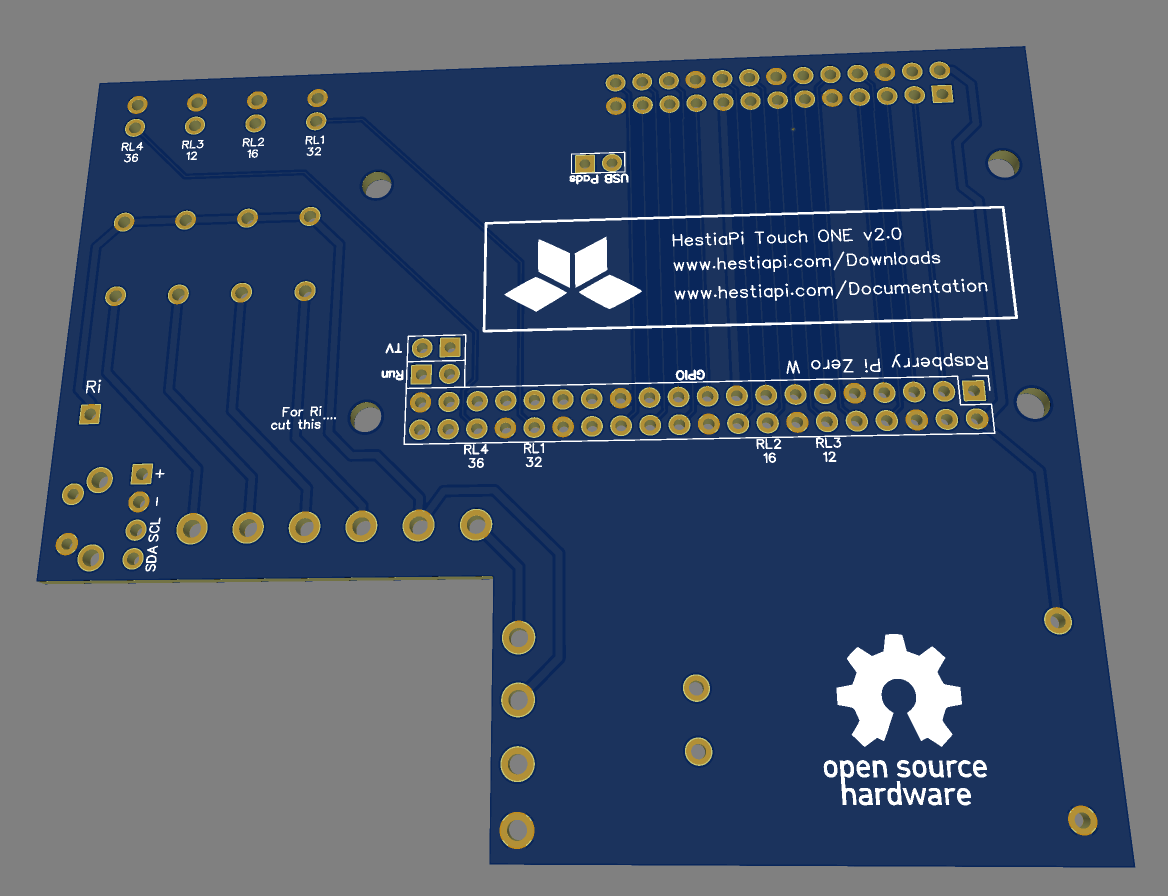
Here is an updated PCB suggestion.
To save space and avoid 7 terminal blocks (it is a number that requires 2 types of terminal blocks 2 x 2 pin + 1 x 3 pin) we add an unpopulated pin Ri (Relay input) on the left of this bottom view of the PCB. When Ri is needed you would need to cut the track labeled “For Ri cut this” and connect one of the two wires you mentioned.
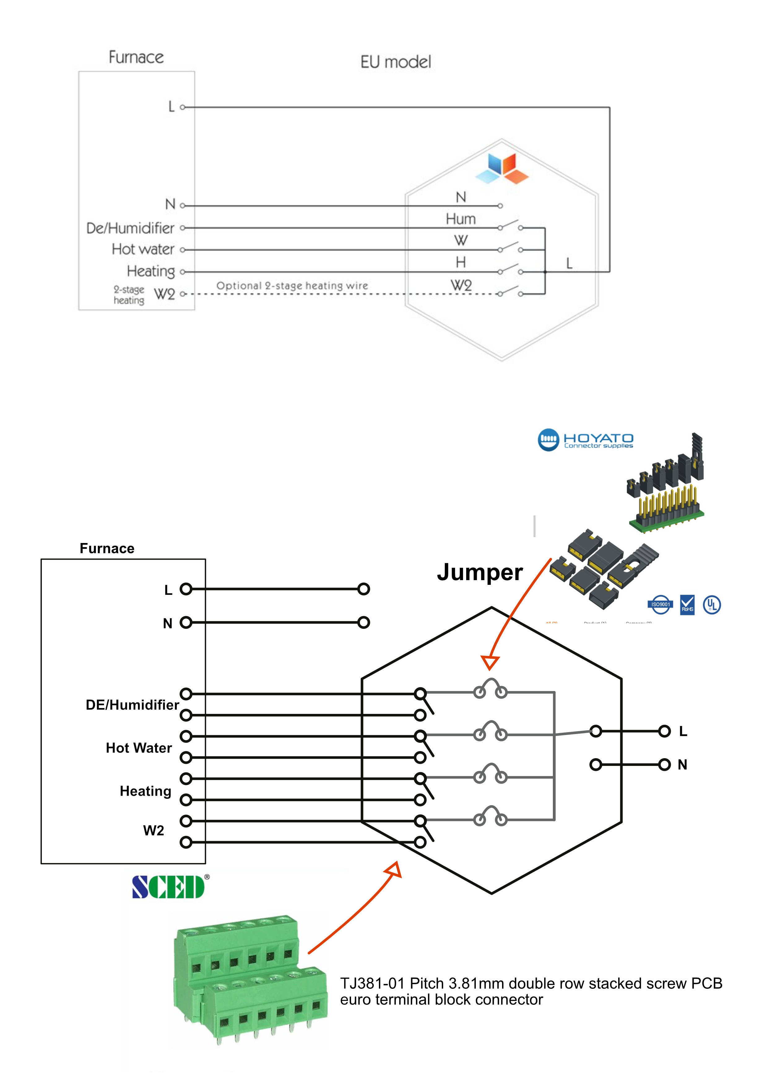
I suggest a different approach, see attached image.
Eventually you may create a jumper to connect line to the one relay pin in case some one need to power the device.
I think that will be a solution more flexible.
I’m not a great fan of jumpers on 220V AC even though we know it’s only a few mA passing through. I have seen users use HestiaPi for all sorts of things. Also if removed it may be open live contacts.
The suggested terminal block is not that “standard” and it may add some extra complexity to a DIYer sourcing the parts.
Let’s leave this here to see how much interest it gets.
If anyone is interested, please comment below.
Of course jumper is an option as is possible to solve the same connection easily outside Hestiapi circuit, the terminal block is just an example or idea, I believe is more interesting to have the 2 out wire from relay available directly on the board, which terminal use I do not know, a two line like one proposed have an limited space impact on the pcb.
In may case I have to put a relay between HestiaPI and furnace, is not a really bug problem, ma I have to find the space where to put it.
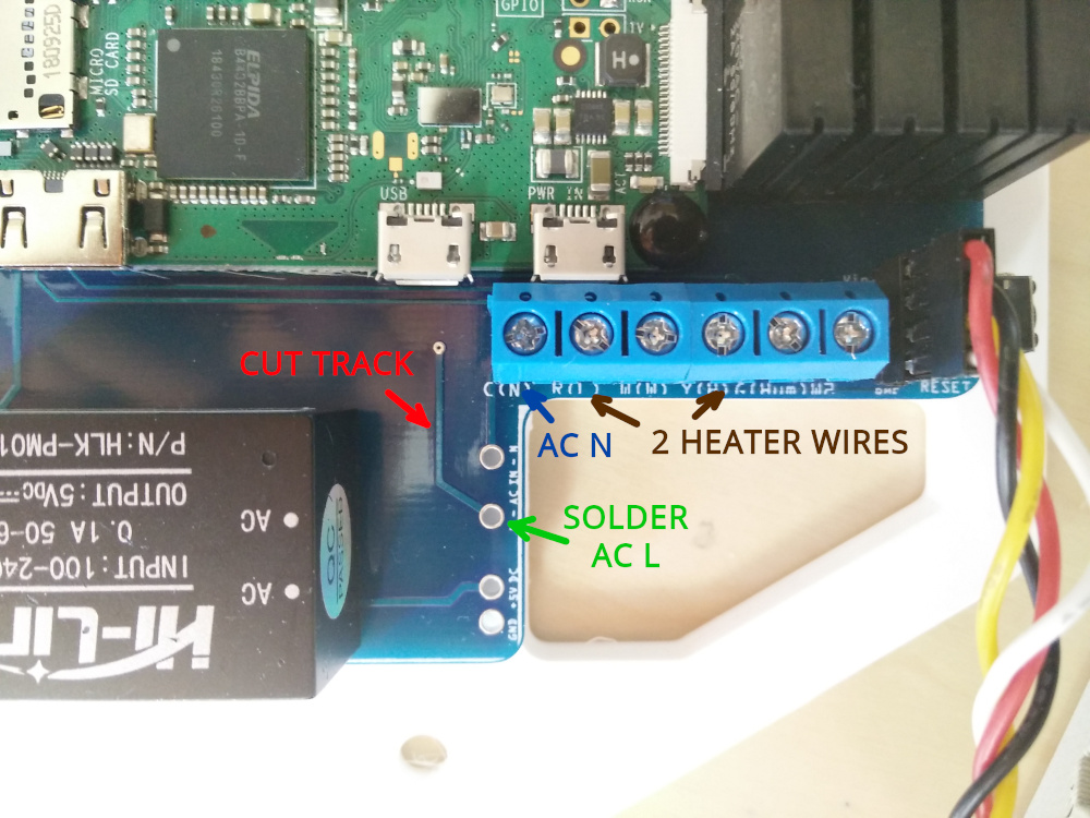
If you only wich to control your boiler, then you can use the EU version of the HestiaPi.
The trick is NOT to solder the transformer on the PCB.
To power the HestiaPi, use a mobile phone power supply and connect it to the micro usb port of the Raspberry Pi. This should also work on the “data” micro usb port of the Raspberry.
Then connect the 2 wires of the boiler to the blocks as described in the thread below: