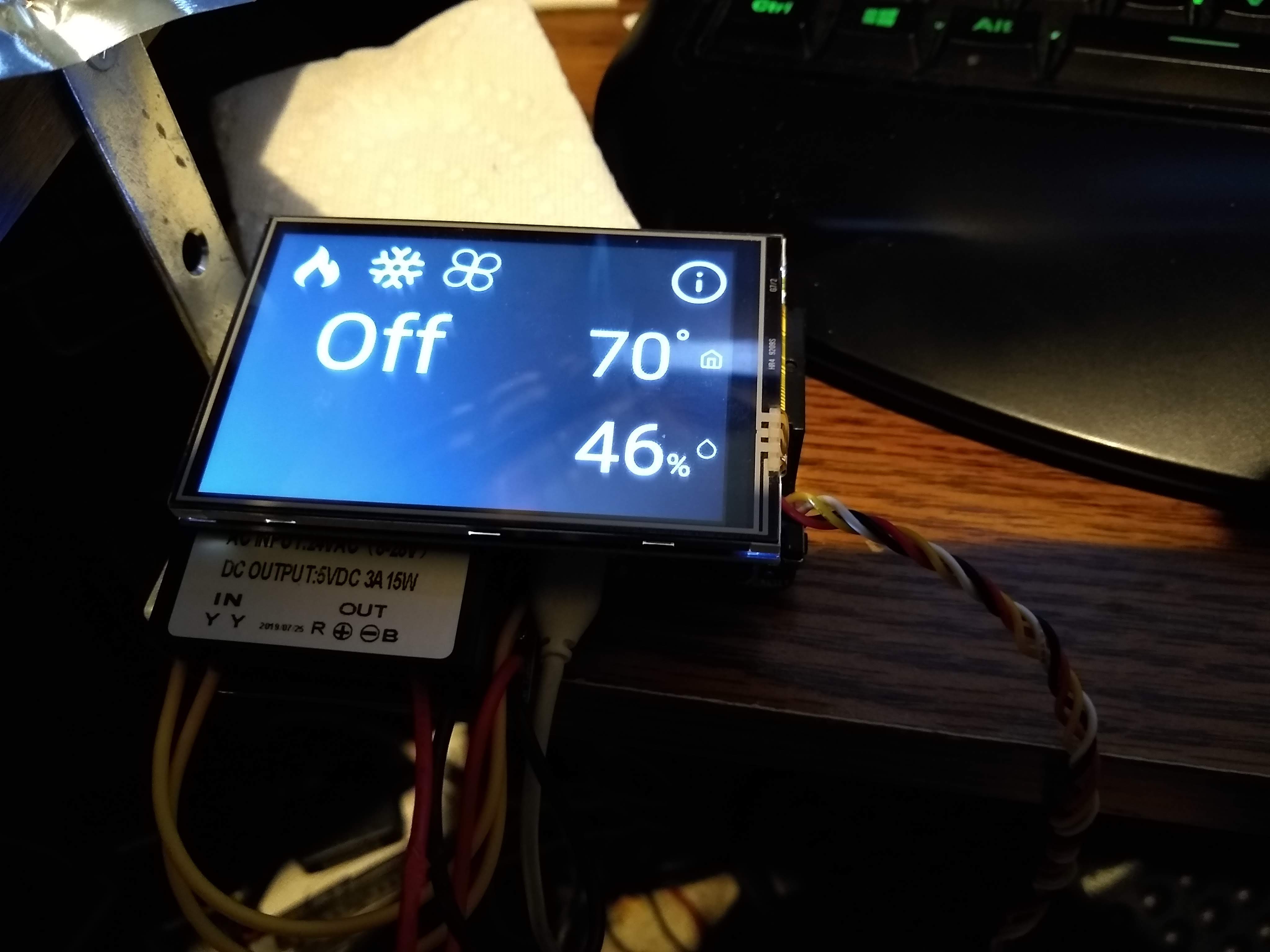
I checked the voltage to the PCB PSU from the HVAC system at 28V AC and the output at 5V DC. However, when I try to boot from it the screen flashes white and light gray constantly. I can see the Pi trying to boot but again the green LED flashes continuously but never finishes booting or displaying anything on the screen. I removed the blue connector block and reconnected the HestiaPi to a USB power supply and all worked perfectly.
Less important
As an aside, one of the connector block terminals also locked fully open and now no longer moves in or out. And, unfortunately, in removing the connector block I also pulled out the White through-hole connection. Both of which I can repair.
I assume we have a bad solder point.
If you can solder, simply refresh the pins from the bottom of the PCB at the Pi’s location (not the LCD). Try and allow the solder to flow in the solder hole of the pin by holding the PCB flat with the solder points facing upwards and simply reheating for 3-4 seconds with a fine soldering tip each pin.
This soldering technique even though it saves space, it caused many issues as some points appeared ok with continuity test before shipping. When the PCB was designed Raspberry Pi Foundation offered Zero W without the headers which made this soldering method very easy. After some months RPi Zero W was only available with the headers presoldered but we thought we could get away with it
1 Like
The above suggested solution still applies. Please try it and comment
OK, give me a few minutes.
I cleaned the flux off the whole board and remade the solder joints and it made no difference. I have an intelligent thermostat (not HestiaPi) that still works perfectly with the HVAC system. Which solder connection did you feel might have caused a problem making the HestiaPi work with the USB source and yet fail with the PSU connected to the HVAC power? At this stage I think the likely culprit is the PSU (as I did originally). I can replace this with a bench 5V DC power supply and see what happens.
The bench power supply worked perfectly. BTW, I have an original Pi Zero W and fitted my own GPIO hammer header.
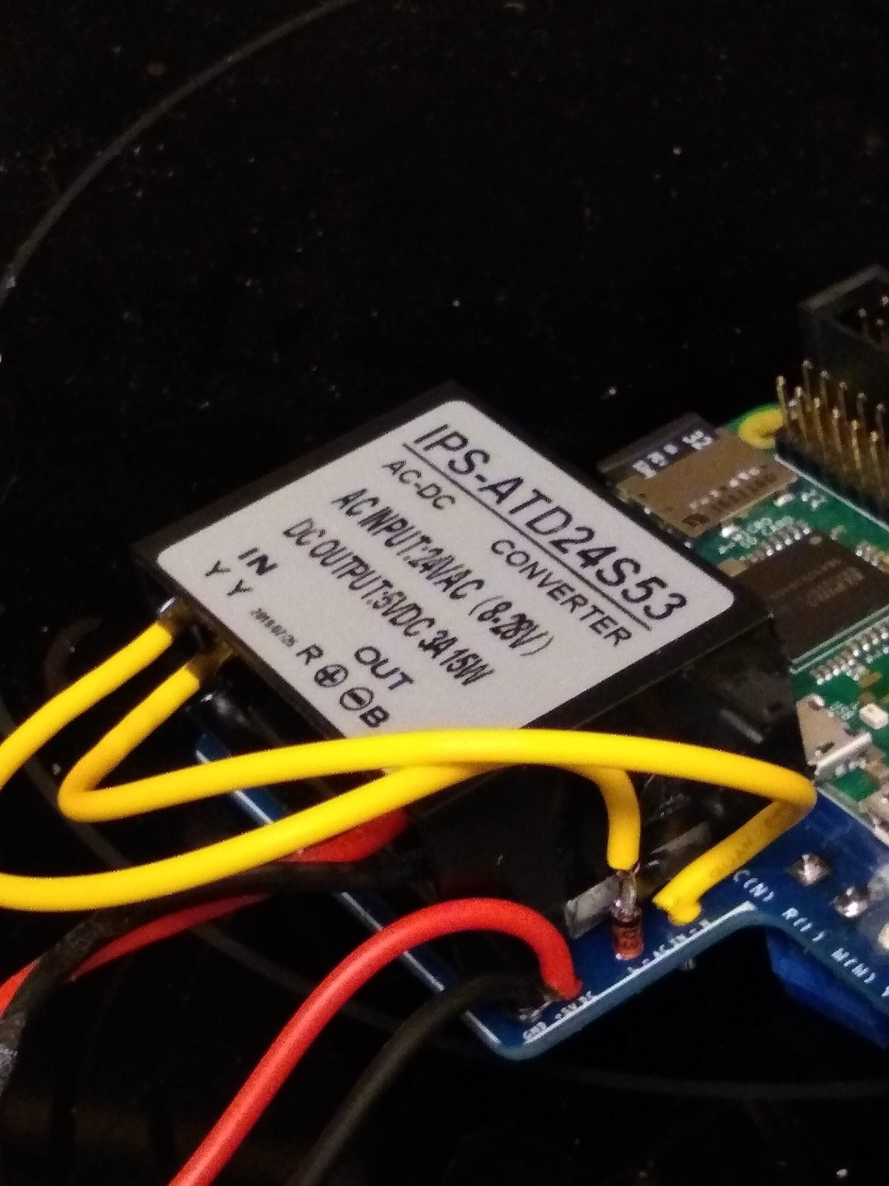
If I had to guess, I think it might be the Input instant Over-Voltage protection. The output of the HVAC transformer is 28V AC and this is right on the upper limit of the PSU (IPS-ATD24S54) input voltage.
We haven’t tested it up to 28V AC to be honest. Most HVAC systems provide a stable 24V AC. Any way you could temporarily find a 24V AC source? Not sure of the specs but a resistor in series could help too but this is something you would need to calculate yourself.
Our response was (immediately after you posted your reply but) before you edited to add the image so we thought that only the Pi was booting OK and the screen was not. It could have been the signal lines but obviously this is not the case here.
I will use a couple of 24V zener diodes. I’ll let you know how it goes on Friday.
There are 400+ apartments here so are you saying that we (or I) have a HVAC system made specially for our complex? Because, I am fairly confident there are many nominal 24V systems producing a little over 28V AC (typically 28.3V).
Apologies. You are probably right. We haven’t tested it up to 28V AC.
This is now working. A single 24V zener diode on the live wire fixed the problem. All Honeywell HVAC systems will likely have this issue. If it is any consolation, Nest thermostats have the same problem as their input is limited to 27.6V AC.
1 Like
According to Honeywell’s manual for the T834C, the voltage can be anywhere from 24-30V AC:
These manual thermostats are very common in older apartments and houses.
As the hardware design was done quite some time ago, studying (erm… spying) other commercial units could have been the source of some of our initial requirements passed to our suppliers until we got feedback from users. Although US has been our main area of users since then, this is the first time someone mentioned it but indeed we realised this is not something to be overlooked. We are currently re-evaluating some of the designs as we move to mass production and little changes like the input range can easily be done now rather than later.
Could you share a more specific digikey/mouser link to help others with the same problem?
https://www.digikey.com/products/en/discrete-semiconductor-products/diodes-zener-single/287?k=24V%20zener%20diode
Thank you for the will and effort to troubleshoot!
Any 24V, through-hole, 0.5W, zener diode will work:
https://www.mouser.com/Semiconductors/Discrete-Semiconductors/Diodes-Rectifiers/Zener-Diodes/_/N-ax1mhZ1yzvvqx?P=1z0z63xZ1yuq6ayZ1yw803n&Ns=Pricing|0
https://www.digikey.com/product-detail/en/vishay-semiconductor-diodes-division/1N5252B-TR/1N5252BVSCT-ND/3104358
Choose from your favorite supplier/manufacturer. The part number will typically show some variation of 1N5252B although many manufacturers have their own naming scheme.
Make sure the cathode (-ve marked by black band) is pointing up:

1 Like